FUEL FILTER REPLACEMENT

Tech Tips
If only replacing the fuel filter element sub-assembly, steps 3 through 6 are not necessary.
-
DISCONNECT CABLE FROM NEGATIVE BATTERY TERMINAL
-
REMOVE FUEL FILTER ELEMENT SUB-ASSEMBLY
-
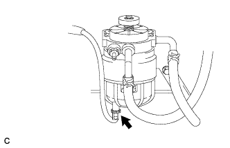
Disconnect the level warning switch connector.
-
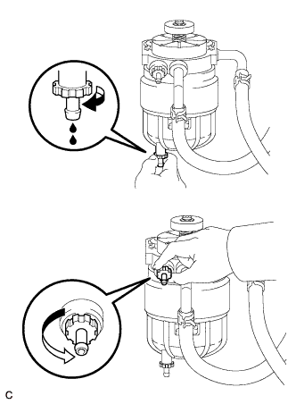
Loosen the drain plug and the air bleed plug as shown in the illustration. Drain the fuel.
Note
-
Do not use any tools.
-
Do not spill any fuel.
-
If any fuel is spilt on any part of the engine, wipe it clean with a shop rag or a piece of cloth.
-
-
When fuel stops draining from the drain plug, tighten the drain plug and air bleed plug.
-
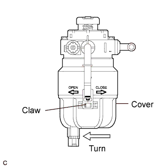
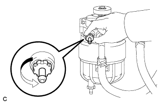
Disengage the claw. Then, remove the cover by turning it counterclockwise approximately 120°.
-
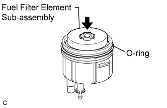
Remove the fuel filter element sub-assembly.
-
Remove the O-ring from the fuel filter cover.
-
-
REMOVE FUEL FILTER ASSEMBLY
-
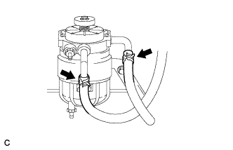
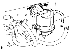
Disconnect the 2 fuel hoses.
-
Remove the 2 bolts and the fuel filter assembly.
-
-
REMOVE FUEL SEDIMENT FILTER ASSEMBLY
-
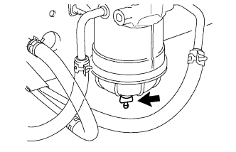
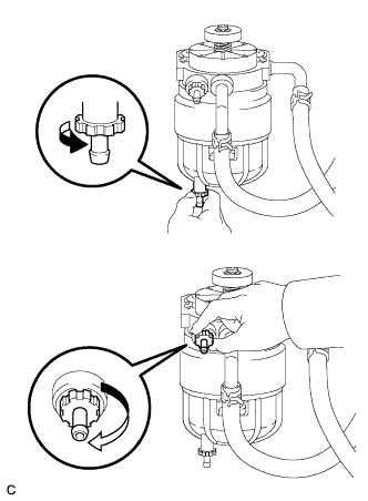
Loosen the drain plug as shown in the illustration. Drain the fuel.
-
When fuel stops draining from the drain plug, tighten the drain plug.
-
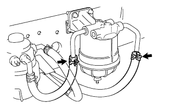
Disconnect the 2 fuel hoses.
-
Remove the 2 bolts and the fuel sediment filter assembly.
-
-
INSTALL FUEL SEDIMENT FILTER ASSEMBLY
-
Install the fuel sediment filter assembly with the 2 bolts.
- Torque:
- 44 N*m { 449 kgf*cm, 33 ft.*lbf }
-
Connect the 2 fuel hoses.
-
-
INSTALL FUEL FILTER ASSEMBLY
-
Install the fuel filter assembly with the 2 bolts.
- Torque:
- 18 N*m { 180 kgf*cm, 13 ft.*lbf }
-
Connect the 2 fuel hoses.
-
-
INSTALL FUEL FILTER ELEMENT SUB-ASSEMBLY
-
Install the fuel filter element sub-assembly to the fuel filter cover.
-
Install the O-ring to the fuel filter cover.
-

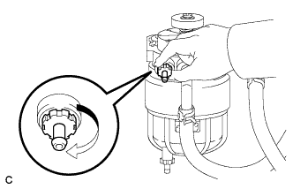
Install the fuel filter cover by turning it clockwise until the claw is engaged.
-
Connect the level warning switch connector.
-
-
BLEED AIR FROM FUEL SYSTEM
-
Loosen the fuel filter's air bleed plug.
-
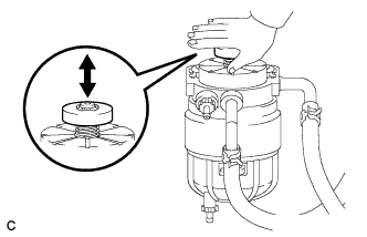
While covering the drain pipe with a shop rag or a piece of cloth, press and release the priming pump until the fuel from the drain pipe does not have any bubbles.
-
Tighten the air bleed plug.
Note
Do not use any tools.
-
-
CONNECT CABLE TO NEGATIVE BATTERY TERMINAL
-
INSPECT FOR FUEL LEAK
-
Perform the Active Test.
-
Replace the normal DLC3 cable (12 V specification) for the intelligent tester with the 24 V DLC3 cable.
Note
Be sure to use the 24 V DLC3 cable when connecting the intelligent tester to the DLC3. Using the normal DLC3 cable (12 V specification) will cause damage to the tester.
-
Connect the intelligent tester to the DLC3.
-
Start the engine.
-
Turn the intelligent tester on.
-
Select the following menu items: Powertrain / Engine / Active Test.
-
Perform the Active Test.
Tester Display Test Part Control Range Diagnostic Notes Test the Fuel Leak Pressurizing common rail internal fuel pressure, and checking for fuel leaks Stop/Start
-
Fuel pressure inside common rail pressurized to specified value and engine speed increased to 2,000 rpm when ON is selected
-
Above conditions preserved while test is ON
-
-
-