COMMON RAIL INSTALLATION

-
INSTALL COMMON RAIL ASSEMBLY
-
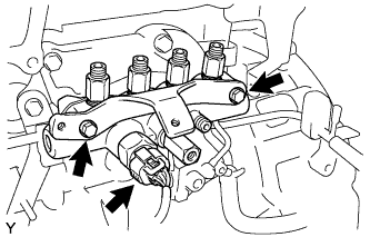
Install the common rail assembly and the No. 3 injection pipe bracket with the 2 bolts.
- Torque:
- 29 N*m { 291 kgf*cm, 21 ft.*lbf }
-
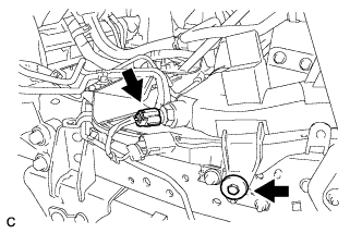
Connect the fuel pressure sensor connector.
-
-
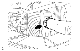
INSTALL FUEL FILTER TO INJECTION PUMP FUEL PIPE
-
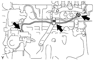
Temporarily install the fuel pipe with the union nuts.
-
Using SST, tighten the union nuts.
- SST
- 09023-12901
- Torque:
- 44 N*m { 449 kgf*cm, 33 ft.*lbf }
Note
Refer to the torque above when not using SST. When using SST, calculate the torque in accordance with the lengths of SST and the torque wrench. Click here
-
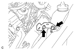
Install the pipe clamp with the nut. Tighten the nut until the clamp's edges make contact with the engine side clamp's edges.
-
-
INSTALL NO. 4 FUEL PIPE SUB-ASSEMBLY
-
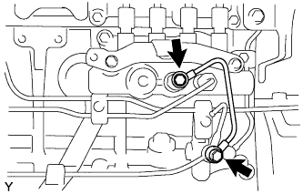
Install 4 new gaskets and the No. 4 fuel pipe with the 2 union bolts.
- Torque:
- 20 N*m { 204 kgf*cm, 15 ft.*lbf, for M10 bolt }
- 25 N*m { 250 kgf*cm, 18 ft.*lbf, for M12 bolt }
-
-
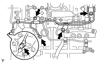
INSTALL INJECTION PIPE SUB-ASSEMBLY
-
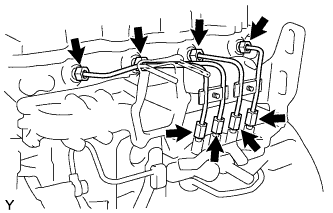
Temporarily install the 4 injection pipes with the union nuts.
-
Using SST, tighten the union nuts.
- SST
- 09023-12901
- Torque:
- 44 N*m { 449 kgf*cm, 33 ft.*lbf }
Note
Refer to the torque above when not using SST. When using SST, calculate the torque in accordance with the lengths of SST and the torque wrench. Click here
-
-
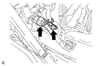
INSTALL INJECTION PIPE CLAMP
-
Apply a light coat of engine oil to the O-ring of oil level dipstick guide.
-
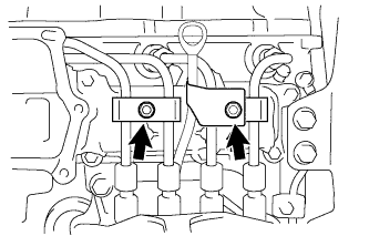
Temporarily install the 2 injection pipe clamps and oil level dipstick guide with the 2 nuts.
-
Tighten the nut until the clamp's edges make contact with the engine side clamp's edges.
-
-
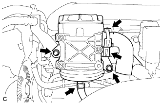
INSTALL VENTURI ASSEMBLY
-
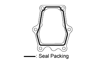
Remove any seal packing material from the contact surface.
-
Apply a continuous bead of seal packing (width: 1.5 to 2.5 mm (0.06 to 0.10 in.)) as shown in the illustration.
Seal packing Toyota Genuine Seal Packing Black, Three Bond 1207B or equivalent Note
-
Remove any oil from the contact surface.
-
Apply seal packing to the inner side of the bolt holes.
-
Install the intake pipe with EGR valve within 3 minutes of applying the seal packing.
-
Do not run the engine for at least 2 hours after installing.
-
-
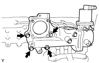
Install the intake pipe with EGR valve with the 4 bolts.
- Torque:
- 29 N*m { 291 kgf*cm, 21 ft.*lbf }
-
-
INSTALL EGR VALVE BRACKET
-
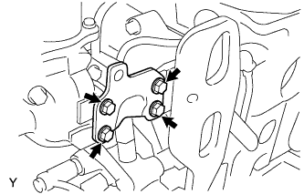
Install the EGR valve bracket with 4 bolts.
- Torque:
- 29 N*m { 291 kgf*cm, 21 ft.*lbf }
-
-
INSTALL OIL SEPARATOR ASSEMBLY
-
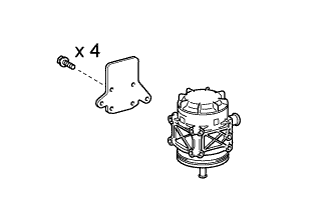
Install the oil separator bracket with the 4 bolts onto the oil separator.
- Torque:
- 29 N*m { 291 kgf*cm, 21 ft.*lbf }
-
Connect the 3 hoses.
-
Install the oil separator assembly with the 2 bolts.
- Torque:
- 29 N*m { 290 kgf*cm, 21 ft.*lbf }
-
Install the harness bracket with the 2 bolts onto the oil separator.
- Torque:
- 29 N*m { 290 kgf*cm, 21 ft.*lbf }
-
-
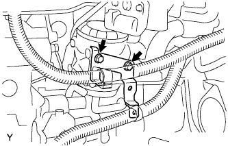
INSTALL VENTILATION PIPE SUB-ASSEMBLY
-
Install the ventilation pipe sub-assembly with the 2 bolts.
-
Connect the 3 hoses.
-
-
INSTALL EGR COOLER SUB-ASSEMBLY
-
Install the EGR cooler with a new gasket and the 2 bolts.
- Torque:
- Flange
- 55 N*m { 560 kgf*cm, 41 ft.*lbf }
- Engine
- 69 N*m { 700 kgf*cm, 51 ft.*lbf }
-
Connect the water by-pass hose.
-
-
INSTALL WATER BY-PASS PIPE SUB-ASSEMBLY
-
Install 4 new gaskets and water by-pass pipe sub-assembly with the 2 union bolts and 3 bolts.
- Torque:
- for Union Bolt
- 25 N*m { 250 kgf*cm, 18 ft.*lbf }
- for Bolt
- 29 N*m { 291 kgf*cm, 21 ft.*lbf }
-
Connect the 2 hoses to the EGR valve.
-
-
CONNECT WIRE HARNESS AND CONNECTORS
-
Connect the 3 connectors.
-
-
INSTALL DIESEL THROTTLE BODY
-
Remove any seal packing material from the contact surface.
-
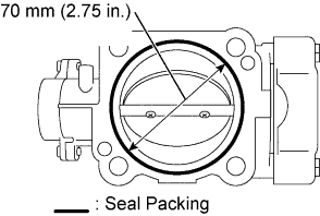
Apply a continuous bead of seal packing (width: 1.5 to 2.5 mm (0.06 to 0.10 in. )) as shown in the illustration.
Tech Tips
-
Remove any oil from the contact surface.
-
Apply seal packing to the inner side of the bolt holes.
-
Install the diesel throttle body assembly within 3 minutes of applying the seal packing.
-
Do not run the engine for at least 2 hours after installing.
-
-
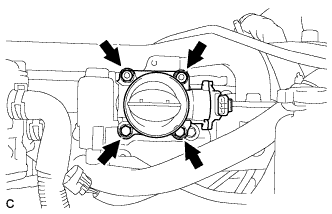
Install the diesel throttle body with the 2 bolts and 2 nuts.
- Torque:
- 29 N*m { 290 kgf*cm, 21 ft.*lbf }
-
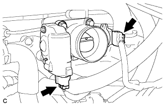
Connect the 2 diesel throttle body connectors.
-
-
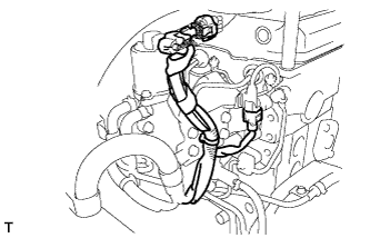
INSTALL INTAKE AIR PIPE NO. 1 WITH AIR HOSE NO. 4
-
Install the No. 1 intake air pipe with No. 4 air hose with the hose band.
-
Install the bolt, and connect the intake air temperature sensor connector.
- Torque:
- 18 N*m { 185 kgf*cm, 13 ft.*lbf }
-
Install the bolt, and connect the turbo pressure sensor connector and wire harness clamp.
- Torque:
- 18 N*m { 185 kgf*cm, 13 ft.*lbf }
-
Install the bracket with the 2 bolts.
- Torque:
- 18 N*m { 185 kgf*cm, 13 ft.*lbf }
-
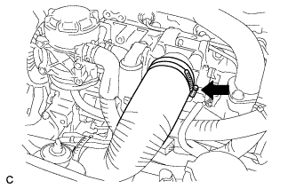
Install the hose band.
-
-
BLEED AIR FROM FUEL SYSTEM
Tech Tips
-
ADD COOLANT
-
CONNECT CABLE TO NEGATIVE BATTERY TERMINAL
-
INSPECT FOR FUEL LEAK
-
Perform the Active Test.
-
Replace the normal DLC3 cable (12 V specification) for the intelligent tester with the 24 V DLC3 cable.
Note
Be sure to use the 24 V DLC3 cable when connecting the intelligent tester to the DLC3. Using the normal DLC3 cable (12 V specification) will cause damage to the tester.
-
Connect the intelligent tester to the DLC3.
-
Start the engine.
-
Turn the intelligent tester on.
-
Select the following menu items: Powertrain / Engine / Active Test.
-
Perform the Active Test.
Tester Display Test Part Control Range Diagnostic Notes Test the Fuel Leak Pressurizing common rail internal fuel pressure, and checking for fuel leaks Stop/Start
-
Fuel pressure inside common rail pressurized to specified value and engine speed increased to 2,000 rpm when ON is selected
-
Above conditions preserved while test is ON
-
-
-
-
INSPECT FOR COOLANT LEAK
-
Remove the radiator cap.
CAUTION:
Do not remove the radiator cap while the engine and radiator are still hot. Pressurized, hot engine coolant and steam may be released and cause serious burns.
-
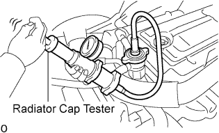
Fill the radiator with coolant and attach a radiator cap tester.
-
Warm up the engine.
-
Using a radiator cap tester, increase the pressure inside the radiator to 137 kPa (1.4 kgf/cm2, 19.9 psi), and check that the pressure does not drop.
If the pressure drops, check the hoses, radiator and water pump for leaks. If no external leaks are found, check the heater core, cylinder block and cylinder head.
-
Install the radiator cap.
-
-
INSPECT FOR OIL LEAK