FUEL SUPPLY PUMP REMOVAL

-
DISCONNECT CABLE FROM NEGATIVE BATTERY TERMINAL
-
SET NO. 1 CYLINDER TO TDC / COMPRESSION
-
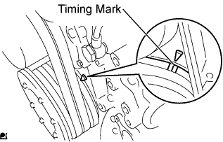
Turn the crankshaft pulley until the grooves of the crankshaft damper and timing gear are aligned.
-
-
REMOVE INTAKE AIR PIPE NO. 1 WITH AIR HOSE NO. 4
-
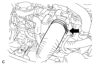
Disconnect the hose band.
-
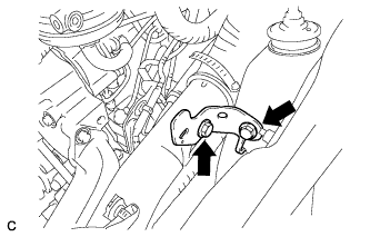
Remove the 2 bolts and bracket.
-
Disconnect the turbo pressure sensor connector and wire harness clamp, and remove the bolt.
-
Disconnect the intake air temperature sensor connector, and remove the bolt.
-
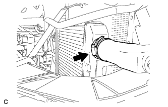
Disconnect the hose band, and remove the No. 1 intake air pipe with No. 4 air hose.
-
-
SEPARATE WIRE HARNESS AND CONNECTORS
-
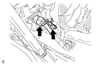
Disconnect the 3 connectors.
-
-
REMOVE VENTILATION PIPE SUB-ASSEMBLY
-
Remove the 2 bolts.
-
Disconnect the 3 hoses and remove the ventilation pipe sub-assembly.
-
-
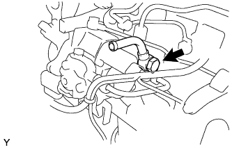
REMOVE OIL SEPARATOR ASSEMBLY
-
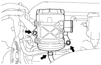
Move the clamp and disconnect the hose.
-
Remove the 2 bolts and the oil separator assembly.
-
-
DISCONNECT FUEL RETURN HOSE
-
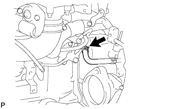
Move the clamp and disconnect the fuel hose.
-
-
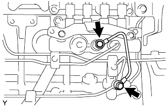
REMOVE FUEL DELIVERY PIPE
-
Remove the union bolt, the 2 gaskets and the fuel delivery pipe.
-
-
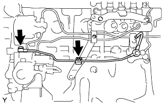
REMOVE NO. 4 FUEL PIPE SUB-ASSEMBLY
-
Remove the 2 union bolts, the 4 gaskets and the No. 4 fuel pipe sub-assembly.
-
-
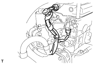
REMOVE FUEL RETURN PIPE SUB-ASSEMBLY
-
Remove the nut and the fuel pipe clamp.
-
Remove the union bolt, the gasket and the fuel return pipe sub-assembly.
-
-
REMOVE FUEL FILTER TO INJECTION PUMP FUEL PIPE
-
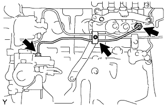
Remove the nut and the fuel pipe clamp.
-
Using SST, loosen the union nuts and remove the fuel filter to injection pump fuel pipe.
- SST
- 09023-12901
-
-
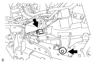
REMOVE CRANK POSITION SENSOR
-
Disconnect the crank position sensor connector.
-
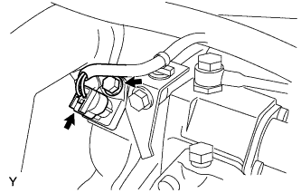
Remove the bolt and crank position sensor.
-
-
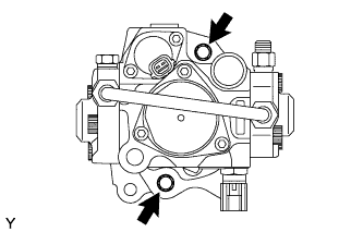
REMOVE INJECTION OR SUPPLY PUMP ASSEMBLY
-
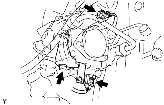
Disconnect the 2 connectors.
-
Remove the bolt and the holder clip.
-
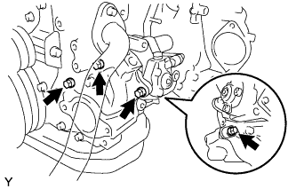
Remove the 4 bolts and the injection or supply pump assembly.
-
Remove the O-ring from the timer cover.
-
-
REMOVE INJECTION PUMP DRIVE GEAR
-

Clamp the injection pump in a soft jaw vise.
-
Remove the nut, the injection pump drive gear and the crankshaft angle sensor plate.
-
Remove the 2 bolts and the timer cover.
-
Remove the O-ring from the timer cover.
-