FUEL INJECTOR REMOVAL

-
INSPECT INJECTOR COMPENSATION CODE
-
Check that the injection compensation code registered in the injector assembly installed on each cylinder matches the one registered in the ECM Click here.
-
If they do not match, follow the procedures below to correct the registration details and recheck the symptom.
-
Correct the registration details by following the procedures in "Resister injection compensation code" Click here.
-
After correcting the registration details, check if the same symptom occurs as when the vehicle was brought in.
Tech Tips
If it does not occur, the symptom may be caused by errors in injection compensation code registration.
-
-
-
DISCONNECT CABLE FROM NEGATIVE BATTERY TERMINAL
-
DRAIN ENGINE COOLANT
CAUTION:
Do not remove the radiator cap sub-assembly while the engine and radiator are still hot. Pressurized, hot engine coolant and steam may be released and cause serious burns.
-
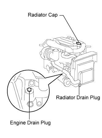
Loosen the radiator drain cock plug and engine drain plug.
-
Remove the radiator cap, then drain the coolant.
-
Close the radiator drain cock plug.
-
Tighten the engine drain plug.
- Torque:
- 27 N*m { 275 kgf*cm, 20 ft.*lbf, for the engine drain plug }
-
-
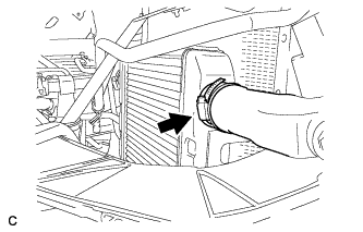
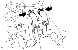
REMOVE NO. 2 INTAKE PIPE
-
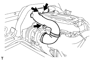
Remove the 3 bolts, loosen the 2 bands, and remove the No. 2 intake pipe.
-
-
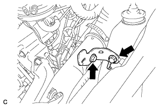
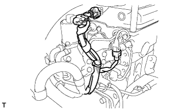
REMOVE VENTILATION PIPE SUB-ASSEMBLY
-
Remove the 2 bolts.
-
Disconnect the 3 hoses and remove the ventilation pipe sub-assembly.
-
-
REMOVE INTAKE AIR PIPE NO. 1 WITH AIR HOSE NO. 4
-
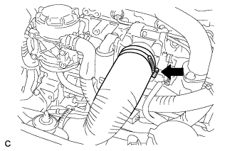
Disconnect the hose band.
-
Remove the 2 bolts and bracket.
-
Disconnect the turbo pressure sensor connector and wire harness clamp, and remove the bolt.
-
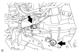
Disconnect the intake air temperature sensor connector, and remove the bolt.
-
Disconnect the hose band, and remove the No. 1 intake air pipe with No. 4 air hose.
-
-
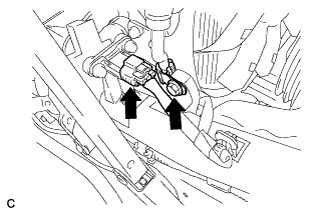
REMOVE DIESEL THROTTLE BODY
-
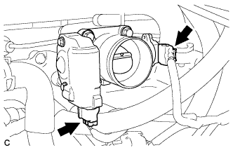
Disconnect the 2 diesel throttle body connectors.
-
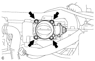
Remove the 2 bolts, 2 nuts and diesel throttle body.
-
-
DISCONNECT WIRE HARNESS AND CONNECTORS
-
Disconnect the 3 connectors.
-
-
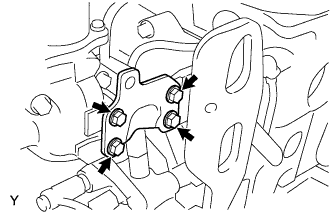
REMOVE WATER BY-PASS PIPE SUB-ASSEMBLY
-
Disconnect the hoses from the EGR valve assembly.
-
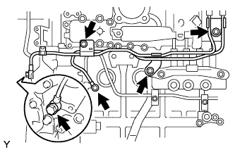
Remove the 3 bolts and 2 union bolts, and separate the water by-pass pipe sub-assembly.
-
-
REMOVE EGR COOLER SUB-ASSEMBLY
-
Separate the water by-pass hose.
-
Remove the 6 bolts and remove the EGR cooler.
-
-
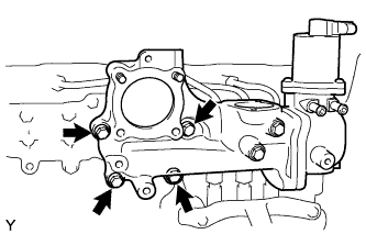
REMOVE EGR VALVE BRACKET
-
Remove the 4 bolts and bracket.
-
-
REMOVE VENTURI ASSEMBLY
-
Remove the 4 bolts and the intake pipe with EGR valve.
-
-
REMOVE OIL FILLER CAP SUB-ASSEMBLY
-

Remove the oil filler cap sub-assembly.
-
-
REMOVE NO. 2 CYLINDER HEAD COVER SUB-ASSEMBLY
-
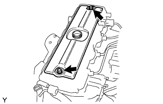
Remove the 2 bolts and remove the No. 2 cylinder head cover sub-assembly.
-
-
REMOVE CYLINDER HEAD COVER SUB-ASSEMBLY
-
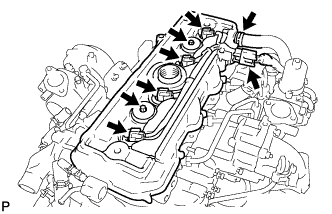
Disconnect the ventilation hose.
-
Disconnect the 5 connectors and remove the wire harness.
-
Remove the cylinder head cover cushion rubber.
-
Remove the 2 bolts, the 2 cushions, and the cylinder head cover.
-
Remove the gasket from the cylinder head cover.
-
-
REMOVE INJECTION PIPE CLAMP
-

Remove the 2 nuts.
-
Remove the oil level dipstick guide and O-ring, then remove the 2 injection pipe clamps.
-
-
REMOVE INJECTION PIPE SUB-ASSEMBLY
-
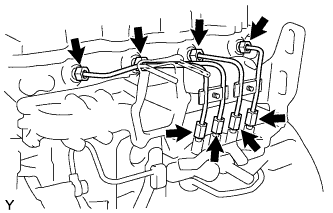
Using SST, loosen the union nuts and remove the 4 injection pipe sub-assemblies.
- SST
- 09023-12901
-
-
REMOVE INJECTOR ASSEMBLY
-
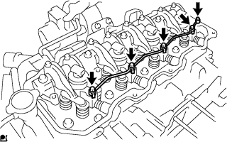
Remove the union bolt, the 4 hollow screws, the 5 gaskets and the nozzle leakage pipe.
Note
After removing the nozzle leakage pipe, put it in a plastic bag to prevent foreign matter from contaminating its injector.
-
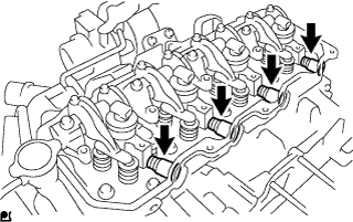
Using a small screwdriver, move the 4 holder seals.
-

Remove the 4 bolts and the 4 nozzle holder clamps.
Note
Arrange the holder clamps and bolts in the correct order.
-
Remove the 4 injectors.
Note
Arrange the injectors in the correct order.
-
Remove the No. 2 cylinder head cover gasket from each injector.
-
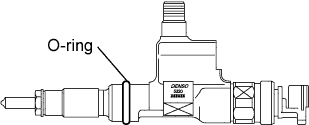
Remove the O-ring from each injector.
-
Remove the 4 injection nozzle seats from the cylinder head.
-