ENGINE UNIT INSTALLATION

-
INSTALL FUEL PIPE SUPPORT
-
Install the fuel pipe support with the 2 bolts.
- Torque:
- 55 N*m { 561 kgf*cm, 41 ft.*lbf }
-
-
INSTALL NO. 2 FUEL PIPE SUPPORT
-
Install the No. 2 fuel pipe support with the 2 bolts.
- Torque:
- 55 N*m { 561 kgf*cm, 41 ft.*lbf }
-
-
INSTALL INTAKE MANIFOLD
-
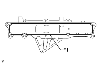
Text in Illustration *1 Seal Packing Apply seal packing to the areas shown in the illustration.
Seal packing Toyota Genuine Seal Packing Black, Three Bond 1207B or equivalent Standard seal diameter 1.5 to 2.5 mm (0.0591 to 0.0984 in.) Note
-
Remove any oil from the contact surface.
-
Install the intake manifold within 5 minutes after applying seal packing.
-
Do not start the engine for at least 2 hours after installation.
-
-
Install the intake manifold with the 8 bolts and 2 nuts.
- Torque:
- 29 N*m { 291 kgf*cm, 21 ft.*lbf }
-
Install the wire harness clamp bracket with the bolt.
- Torque:
- 29 N*m { 291 kgf*cm, 21 ft.*lbf }
-
Install the wire harness clamp bracket with the 2 bolts.
- Torque:
- 29 N*m { 291 kgf*cm, 21 ft.*lbf }
-
Cold Area Specification Vehicles:
Attach the 2 clamps.
-
-
INSTALL EXHAUST MANIFOLD
-
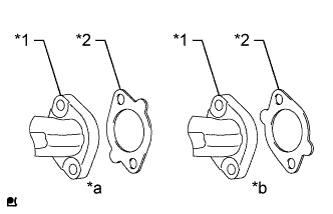
Text in Illustration *1 Exhaust Manifold *2 Gasket *a INCORRECT *b CORRECT Install 4 new gaskets to the cylinder head sub-assembly as shown in the illustration.
-
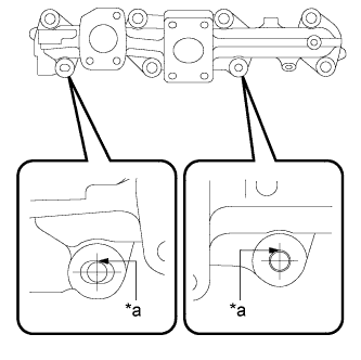
Text in Illustration *a Contact Temporarily install the exhaust manifold.
Tech Tips
The stud bolts should contact the exhaust manifold as shown in the illustration.
-
Temporarily install 8 new nuts and the 8 spacers to the exhaust manifold.
Tech Tips
Be sure to install the spacers for the positions labeled A in the orientation shown in the illustration.
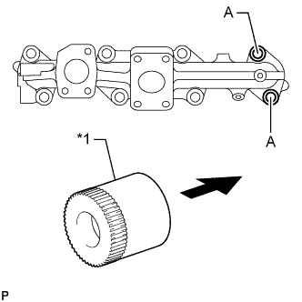
Text in Illustration *1 Spacer 
Engine Side -
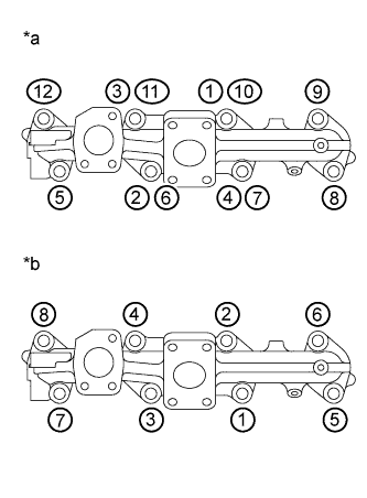
Text in Illustration *a New Exhaust Manifold *b Used Exhaust Manifold Tighten the nuts in the order shown in the illustration.
- Torque:
- 60 N*m { 612 kgf*cm, 44 ft.*lbf }
-
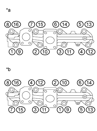
Text in Illustration *a New Exhaust Manifold *b Used Exhaust Manifold Retighten the nuts in the order shown in the illustration.
- Torque:
- 60 N*m { 612 kgf*cm, 44 ft.*lbf }
-
-
INSTALL OIL COOLER ASSEMBLY
-
INSTALL FRONT ENGINE MOUNTING INSULATOR
-
Install the 2 front engine mounting insulators and 2 engine mounting stabilizers with the 2 nuts.
- Torque:
- 98 N*m { 999 kgf*cm, 72 ft.*lbf }
-
-
INSTALL ENGINE WATER PUMP ASSEMBLY
-
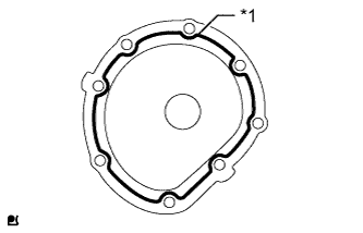
Text in Illustration *1 Seal Packing Apply a continuous bead of seal packing (diameter 2.2 to 2.7 mm (0.0866 to 0.106 in.)) as shown in the illustration.
Seal packing Toyota Genuine Seal Packing Black, Three Bond 1207B or equivalent Seal diameter 2.2 to 2.7 mm (0.0866 to 0.106 in.) Note
-
Remove any oil from the contact surfaces.
-
Install the engine water pump assembly within 3 minutes of applying the seal packing.
-
Do not start the engine for at least 2 hours after the installation.
-
-
Install the engine water pump assembly with the 8 bolts.
- Torque:
- 29 N*m { 291 kgf*cm, 21 ft.*lbf }
-
-
INSTALL WATER BY-PASS PIPE SUB-ASSEMBLY
-
Install 6 new O-rings and the water by-pass pipe sub-assembly with the 6 bolts.
- Torque:
- 21 N*m { 291 kgf*cm, 21 ft.*lbf }
-
-
INSTALL WATER OUTLET HOUSING
-
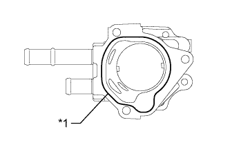
Text in Illustration *1 Seal Packing Apply seal packing in a continuous line as shown in the illustration.
Seal packing Toyota Genuine Seal Packing Black, Three Bond 1207B or equivalent. Standard seal diameter 2.5 mm (0.0984 in.) Note
-
Remove any oil from the contact surface.
-
Install the water outlet housing within 3 minutes of applying the seal packing.
-
Do not start the engine for at least 2 hours after the installation.
-
-
Install the water outlet housing with the 3 bolts.
- Torque:
- 29 N*m { 291 kgf*cm, 21 ft.*lbf }
-
-
INSTALL WATER TEMPERATURE SENDER GAUGE ASSEMBLY
-

Install a new gasket to the engine coolant temperature sensor.
-
Using a 19 mm deep socket wrench, install the engine coolant temperature sensor.
- Torque:
- 30 N*m { 301 kgf*cm, 22 ft.*lbf }
-
-
INSTALL THERMOSTAT
-
Install a new gasket to the thermostat.
-
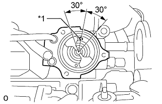
Text in Illustration *1 Jiggle Valve Position the jiggle valve as shown in the illustration and install the thermostat.
-
Install the water outlet with the 3 bolts.
- Torque:
- 29 N*m { 290 kgf*cm, 21 ft.*lbf }
-
-
INSTALL CRANKSHAFT POSITION SENSOR
-
Apply a light coat of engine oil to the O-ring of the crankshaft position sensor.
Note
When reusing the crankshaft position sensor, inspect the O-ring.
-
Install the crankshaft position sensor with the bolt.
- Torque:
- 10 N*m { 102 kgf*cm, 7 ft.*lbf }
Note
Make sure that the O-ring is not cracked and does not come out of position during installation.
-
Connect the crankshaft position sensor connector.
-
-
INSTALL CAMSHAFT POSITION SENSOR
-
Apply a light coat of engine oil to the O-ring of the camshaft position sensor.
Note
When reusing the camshaft position sensor, inspect the O-ring.
-
Install the camshaft position sensor with the bolt.
- Torque:
- 10 N*m { 102 kgf*cm, 7 ft.*lbf }
Note
Make sure that the O-ring is not cracked and does not come out of position during installation.
-
Connect the camshaft position sensor connector.
-
-
INSTALL FUEL FILTER BRACKET
-
Install the fuel filter bracket with the 2 bolts.
- Torque:
- 29 N*m { 291 kgf*cm, 21 ft.*lbf }
-
-
INSTALL FUEL PIPE SUPPORT
-
Install the fuel pipe support with the bolt.
- Torque:
- 29 N*m { 291 kgf*cm, 21 ft.*lbf }
-
-
INSTALL VACUUM PUMP ASSEMBLY
-
Install a new O-ring to the vacuum pump assembly.
-
Install the vacuum pump with the 2 nuts.
- Torque:
- 55 N*m { 561 kgf*cm, 41 ft.*lbf }
-
-
INSTALL VACUUM PUMP OIL PIPE SUB-ASSEMBLY
-
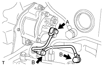
Install 3 new gaskets and the vacuum pump oil pipe sub-assembly with the 3 union bolts.
- Torque:
- for union bolt A
- 13 N*m { 130 kgf*cm, 10 ft.*lbf }
- for union bolt B
- 20 N*m { 200 kgf*cm, 14 ft.*lbf }
-
-
INSTALL VACUUM PIPE
-
Install 2 new gaskets and the vacuum pipe with the union bolt and bolt.
- Torque:
- for union bolt
- 13 N*m { 130 kgf*cm, 10 ft.*lbf }
- for bolt
- 29 N*m { 291 kgf*cm, 21 ft.*lbf }
-
-
INSTALL UPPER FUEL FILTER BODY
-
Install the upper fuel filter body with the 2 bolts.
- Torque:
- 55 N*m { 561 kgf*cm, 41 ft.*lbf }
-
-
INSTALL DIESEL FUEL FILTER ASSEMBLY
-
Check and clean the diesel fuel filter installation surface.
-
Apply clean fuel to the O-ring of a new diesel fuel filter assembly.
-
Tighten the filter by hand until the O-ring contacts the installation surface.
-
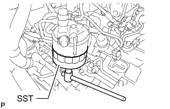
Using SST, tighten the fuel filter an additional 2/3 of a turn after the O-ring contacts the installation surface.
- SST
- 09228-78010
-
-
INSTALL NO. 4 FUEL PIPE SUB-ASSEMBLY
-
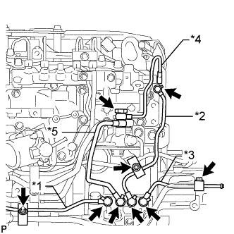
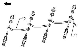
Text in Illustration *1 Fuel Return Pipe Sub-assembly *2 No. 3 Nozzle Leakage Pipe Sub-assembly *3 No. 2 Fuel Return Pipe Sub-assembly *4 Fuel Pipe *5 No. 4 Fuel Pipe Sub-assembly Install a new gasket and the No. 4 fuel pipe sub-assembly with the union bolt.
- Torque:
- 20 N*m { 200 kgf*cm, 14 ft.*lbf }
-
-
INSTALL FUEL PIPE
-
Install 3 new gaskets and the fuel pipe with the union bolt.
- Torque:
- 25 N*m { 250 kgf*cm, 18 ft.*lbf }
-
-
INSTALL NO. 2 FUEL RETURN PIPE SUB-ASSEMBLY
-
Install a new gasket and the No. 2 fuel return pipe sub-assembly with the union bolt.
- Torque:
- 20 N*m { 200 kgf*cm, 14 ft.*lbf }
-
Install the injection pipe clamp with the nut.
- Torque:
- 29 N*m { 291 kgf*cm, 21 ft.*lbf }
-
-
INSTALL NO. 3 NOZZLE LEAKAGE PIPE SUB-ASSEMBLY
-
Install 2 new gaskets and the No. 3 nozzle leakage pipe sub-assembly with the 2 union bolts.
- Torque:
- for cylinder head side
- 13 N*m { 130 kgf*cm, 9 ft.*lbf }
- for No. 2 fuel pipe support side
- 20 N*m { 200 kgf*cm, 14 ft.*lbf }
-
Install the nozzle leakage clamp with the nut.
- Torque:
- 29 N*m { 291 kgf*cm, 21 ft.*lbf }
-
-
INSTALL FUEL RETURN PIPE SUB-ASSEMBLY
-
Install a new gasket and the fuel return pipe sub-assembly with the union bolt.
- Torque:
- 20 N*m { 200 kgf*cm, 14 ft.*lbf }
-
Install the injection pipe clamp with the nut.
- Torque:
- 29 N*m { 291 kgf*cm, 21 ft.*lbf }
-
-
INSTALL INJECTION OR SUPPLY PUMP ASSEMBLY
-
INSTALL INJECTOR ASSEMBLY
-
INSTALL COMMON RAIL ASSEMBLY
-
INSTALL NO. 1 COMPRESSOR MOUNTING BRACKET
-
Install the No. 1 compressor mounting bracket with the 3 bolts.
- Torque:
- 55 N*m { 561 kgf*cm, 41 ft.*lbf }
-
-
INSTALL IDLE PULLEY BRACKET
-
Install the idle pulley bracket with the 3 bolts.
- Torque:
- 55 N*m { 561 kgf*cm, 41 ft.*lbf }
-
-
INSTALL TURBOCHARGER SUB-ASSEMBLY
-
INSTALL RADIATOR PIPE SUB-ASSEMBLY
-
Install a new O-ring to the radiator pipe sub-assembly.
-
Install the radiator pipe sub-assembly with the 2 bolts.
- Torque:
- 29 N*m { 291 kgf*cm, 21 ft.*lbf }
-
-
INSTALL VANE PUMP ASSEMBLY
-
INSTALL BOLT
-
Install the 4 bolts to the 4 glow plug holes.
- Torque:
- 23 N*m { 229 kgf*cm, 17 ft.*lbf }
-
-
INSTALL GLOW PLUG ASSEMBLY (for Cold Area Specification Vehicles)
-
Using a 12 mm deep socket wrench, install the 4 glow plug assemblies.
- Torque:
- 23 N*m { 229 kgf*cm, 17 ft.*lbf }
-
-
INSTALL GLOW PLUG GROUND WIRE (for Cold Area Specification Vehicles)
-
Text in Illustration *1 Wire Harness *2 Glow Plug Ground Wire Engine Front Side Install the 3 glow plug ground wires so that they overlap as shown in the illustration. Make sure that the glow plug ground wire on the front side of the engine is installed first.
Note
If the glow plug ground wires are not installed in the correct order, they may become deformed when the nuts are tightened.
-
Install the wire harness to the No. 4 glow plug.
-
Install the 4 nuts.
- Torque:
- 1.3 N*m { 13 kgf*cm, 11 in.*lbf }
Note
Check that the glow plug ground wires do not interfere with the cylinder head or intake manifold.
-
Install the 4 screw grommets.
-
-
INSTALL NO. 1 INTAKE PIPE
-
Install the No. 1 intake pipe with the 3 bolts and 2 nuts.
- Torque:
- 29 N*m { 291 kgf*cm, 21 ft.*lbf }
-
-
INSTALL VENTURI ASSEMBLY
-
INSTALL EGR VALVE ASSEMBLY
-
INSTALL NO. 2 CYLINDER HEAD COVER SUB-ASSEMBLY
-
Install 4 new No. 2 cylinder head cover gaskets to the 4 injector assemblies.
-
Install a new cylinder head cover gasket and the No. 2 cylinder head cover sub-assembly.
-
Install the 2 cylinder head cover cushions and 2 spacers to the No. 2 cylinder head cover sub-assembly with the 2 bolts.
- Torque:
- 29 N*m { 291 kgf*cm, 21 ft.*lbf }
-
Install the cylinder head cover cushion rubber to the No. 2 cylinder head cover sub-assembly.
-
Connect the 4 connectors and install the wire harness with the bolt.
- Torque:
- 29 N*m { 291 kgf*cm, 21 ft.*lbf }
-
-
INSTALL CYLINDER HEAD COVER SUB-ASSEMBLY
-
Install the 2 cylinder head cover stays and cylinder head cover sub-assembly with the 2 bolts.
- Torque:
- 29 N*m { 291 kgf*cm, 21 ft.*lbf }
-
-
INSTALL OIL FILLER CAP SUB-ASSEMBLY