ENGINE UNIT REASSEMBLY

-
INSTALL REAR ENGINE OIL SEAL
-
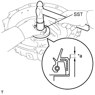
Text in Illustration *a 4 mm (0.157 in.) Using SST and a hammer, tap in a new rear engine oil seal until it is 4 mm (0.157 in.) below the upper edge of the flywheel housing.
- SST
- 09223-78010
Note
-
Be careful not to tap the rear engine oil seal at an angle.
-
Keep the gap between the rear oil seal retainer edge and the rear engine oil seal free of foreign matter.
-
Apply MP grease to the oil seal lip.
-
-
INSTALL FLYWHEEL HOUSING
-
Remove any oil or seal packing material from the contact surfaces.
-
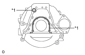
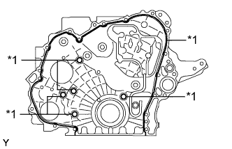
Text in Illustration *1 Seal Packing Apply a continuous bead of seal packing (diameter: 2.0 mm (0.0787 in.)) as shown in the illustration.
Seal packing Toyota Genuine Seal Packing Black, Three Bond 1207B or equivalent Note
-
Remove any oil from the contact surfaces.
-
Install the flywheel housing within 3 minutes of applying the seal packing.
-
Do not expose the seal packing to engine oil for at least 2 hours after installing the flywheel housing.
-
-
Install the flywheel housing with the 14 bolts.
- Torque:
- for M14 bolt
- 132 N*m { 1346 kgf*cm, 97 ft.*lbf }
- for M8 bolt
- 29 N*m { 291 kgf*cm, 21 ft.*lbf }
-
-
INSTALL FLYWHEEL RING GEAR
-
Using a torch, heat the flywheel ring gear evenly to approximately 200°C (392°F).
Note
Be careful not to overheat the flywheel ring gear.
-
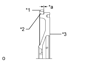
Text in Illustration *1 Chamfer *2 Flywheel Ring Gear *3 Flywheel Sub-assembly *a 0.25 mm (0.00984 in.) or less Using a brass bar, strike the flywheel ring gear onto the flywheel sub-assembly with its chamfered gear teeth facing the block.
Standard clearance 0.25 mm (0.00984 in.) or less CAUTION:
After installing the flywheel ring gear, allow it to cool before handling it.
-
-
INSTALL FLYWHEEL SUB-ASSEMBLY
-
Insert the flywheel sub-assembly slowly until it contacts the collar knock in order to prevent impact with the guide bar. Adjust the position of the flywheel and insert it completely.
Note
The flywheel sub-assembly is heavy. When installing the flywheel sub-assembly, be careful not to drop it.
-
Apply a light coat of engine oil to the threads of the flywheel bolts and flywheel bolt seats.
-
Temporarily install the flywheel with the flywheel bolts.
-
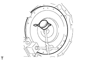
Step 1:
-
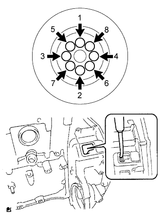
Tighten the flywheel bolts in several steps in the order shown in the illustration.
- Torque:
- 86 N*m { 877 kgf*cm, 63 ft.*lbf }
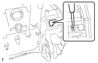
Tech Tips
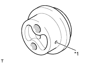
Insert a screwdriver through the inspection hole of the flywheel housing into the ring gear of the flywheel sub-assembly to prevent the ring gear from turning together with the crankshaft.
-
-
Step 2:
-
Mark the top of each flywheel bolt head with paint.
-
Tighten the bolts 45° in the order shown in the illustration.
-
Check that the paint marks are now at a 45° angle to the top.
-
-
Using a dial indicator, measure the runout of the flywheel.
Maximum runout 0.15 mm (0.00591 in.) If the runout is more than the maximum, resurface the flywheel surface.
-
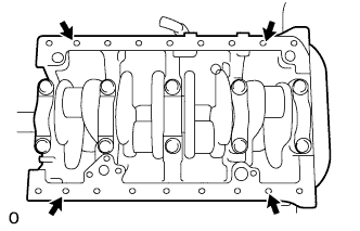
Temporarily install the 4 bolts in the positions on the cylinder block shown in the illustration to prevent the cables from sliding toward the center of the cylinder block.
-
Attach the 2 cables to the cylinder block.
Tech Tips
The cables must be attached outside the installed bolts.
-
Using a chain block and engine sling device, install the cylinder block to an engine stand.
-
Remove the 4 bolts from the cylinder block.
-
-
INSTALL OIL CHECK VALVE SUB-ASSEMBLY
-
Install a new gasket and the oil check valve sub-assembly.
- Torque:
- 42 N*m { 423 kgf*cm, 31 ft.*lbf }
-
-
INSTALL FRONT END PLATE
-
Install a new gasket and the front end plate with the 4 bolts.
- Torque:
- 29 N*m { 291 kgf*cm, 21 ft.*lbf }
-
-
INSTALL OIL PUMP ASSEMBLY
-
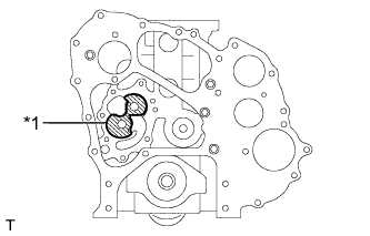
Text in Illustration *1 Engine Oil Apply engine oil to the oil pump case of the cylinder block shown in the illustration.
Note
If engine oil is not applied, an oil suction malfunction will occur when starting the engine. The malfunction will cause seizure or abnormal wear to the engine.
-
Install a new gasket and the oil pump with the 7 bolts.
- Torque:
- 29 N*m { 291 kgf*cm, 21 ft.*lbf }
-
Check that the oil pump rotates smoothly by hand after installation.
-
-
INSTALL CRANKSHAFT TIMING GEAR OR SPROCKET
-
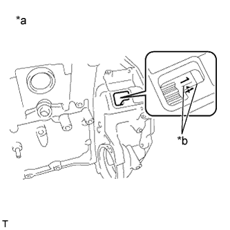
Text in Illustration *a No. 1, No. 4 Cylinder *b Alignment Mark Turn the crankshaft clockwise, and align the alignment mark on the flywheel sub-assembly with the alignment mark between the 2 numbers on the edge of the flywheel housing to set the No. 1 cylinder to TDC/compression.
-
Align the set key on the crankshaft with the key groove of the crankshaft timing gear or sprocket.
-
Using a hammer, tap on the crankshaft timing gear or sprocket.
-
-
INSTALL NO. 1 IDLE GEAR SUB-ASSEMBLY
-
Install the No. 1 idle gear sub-assembly and No. 1 idle gear thrust plate to the No. 1 idle gear shaft.
-
With the No. 1 idle gear shaft oil hole facing down, match the alignment marks for each gear, and insert the shaft into the cylinder block.
Text in Illustration *a Alignment Mark Note
If the oil hole is not facing down, it will cause oil burning or abnormal engine wear.
Text in Illustration *1 Oil Hole -
Tighten the bolt.
- Torque:
- 137 N*m { 1397 kgf*cm, 101 ft.*lbf }
-
-
INSTALL CAMSHAFT
-
Apply engine oil to the camshaft journals and bearings.
-
Text in Illustration *a Alignment Mark Match the alignment marks of the camshaft timing gear and oil pump gear, and install the camshaft.
-
-
INSTALL NO. 2 IDLE GEAR SHAFT
-
Install a new O-ring to the No. 2 idle gear shaft.
-
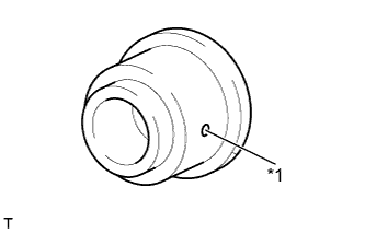
Text in Illustration *1 Oil Hole With the No. 2 idle gear shaft oil hole facing down, install the No. 2 idle gear shaft to the lock plate with the 3 bolts.
- Torque:
- 55 N*m { 561 kgf*cm, 41 ft.*lbf }
Note
If the oil hole is not facing down, it will cause oil burning or abnormal engine wear.
-
-
INSTALL NO. 2 IDLE GEAR SUB-ASSEMBLY
-
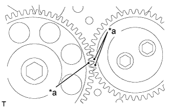
Text in Illustration *a Alignment Mark Match the alignment marks of the No. 1 idle gear sub-assembly and No. 2 idle gear sub-assembly, and install the No. 2 idle gear sub-assembly.
-
-
INSTALL NO. 2 IDLE GEAR THRUST PLATE
-
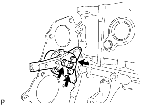
Install the No. 2 idle gear thrust plate with the 2 bolts.
- Torque:
- 55 N*m { 561 kgf*cm, 41 ft.*lbf }
-
-
INSTALL TIMING CHAIN OR BELT COVER OIL SEAL
-
Apply MP grease to the timing chain or belt cover oil seal lip.
-
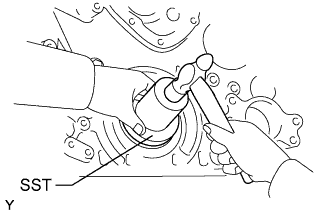
Using SST and a hammer, tap in a new timing chain or belt cover oil seal to the timing gear case so that the timing chain or belt cover oil seal is flush with the timing gear case edge.
- SST
- 09223-78010
Note
-
Be careful not to tap the timing chain or belt cover oil seal at an angle.
-
Keep the gap between the timing gear case edge and the timing chain or belt cover oil seal free of foreign matter.
-
-
INSTALL TIMING GEAR CASE
-
Remove any seal packing material from the contact surfaces.
-
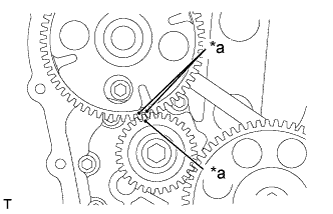
Text in Illustration *1 Seal Packing Apply seal packing in a continuous line as shown in the illustration.
Seal packing Toyota Genuine Seal Packing Black, Three Bond 1207B or equivalent Standard seal diameter 2.5 mm (0.984 in.) Note
-
Remove any oil from the contact surfaces.
-
Install the timing gear case within 3 minutes of applying the seal packing.
-
Do not expose the seal packing to engine oil for at least 2 hours after installation.
-
-
Install the timing gear case with the 15 bolts.
- Torque:
- 29 N*m { 291 kgf*cm, 21 ft.*lbf }
-
-
INSTALL OIL SEPARATOR ASSEMBLY
-
Install 3 new O-rings to the timing gear case and cylinder block.
-
Install the oil separator assembly with the 5 bolts.
- Torque:
- 55 N*m { 561 kgf*cm, 41 ft.*lbf }
-
-
INSTALL CRANKSHAFT PULLEY
-
Using a 46 mm socket wrench, remove the nut, spacer and crankshaft pulley.
Tech Tips
Insert a screwdriver through the inspection hole of the flywheel housing into the ring gear of the flywheel sub-assembly to prevent the ring gear from turning together with the crankshaft.
-
-
INSTALL OIL STRAINER SUB-ASSEMBLY
-
Install a new O-ring to the cylinder block.
-
Install the oil strainer sub-assembly with the 3 bolts.
- Torque:
- 29 N*m { 291 kgf*cm, 21 ft.*lbf }
-
-
INSTALL OIL PAN SUB-ASSEMBLY
-
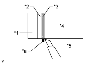
Text in Illustration *1 Timing Gear Case *2 Front End Plate *3 Gasket *4 Cylinder Block *5 Cutter *a Cut Using a cutter, cut the gasket so that it is flush with the lower surface of the cylinder block.
-
Remove seal packing material from the contact surfaces.
-
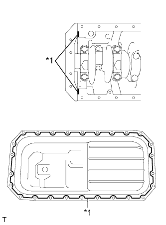
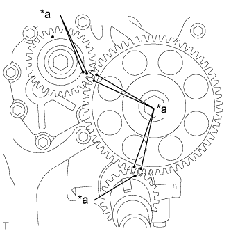
Text in Illustration *1 Seal Packing Apply seal packing in a continuous line as shown in the illustration.
Seal packing Toyota Genuine Seal Packing Black, Three Bond 1207B or equivalent Standard seal diameter 3.5 mm (0.138 in.) Note
-
Remove any oil from the contact surfaces.
-
Install the oil pan sub-assembly within 3 minutes of applying the seal packing.
-
Do not expose the seal packing to engine oil for at least 2 hours after installation.
-
-
Install the oil pan sub-assembly with the 26 bolts.
- Torque:
- 29 N*m { 291 kgf*cm, 21 ft.*lbf }
-
-
INSTALL FLYWHEEL HOUSING STAY RH
-
Install the flywheel housing stay RH with the 4 bolts.
- Torque:
- for M14 bolt
- 132 N*m { 1349 kgf*cm, 97 ft.*lbf }
- for M12 bolt
- 97 N*m { 989 kgf*cm, 72 ft.*lbf }
-
-
INSTALL FLYWHEEL HOUSING STAY LH
-
Install the flywheel housing stay LH with the 4 bolts.
- Torque:
- for M14 bolt
- 132 N*m { 1349 kgf*cm, 97 ft.*lbf }
- for M12 bolt
- 97 N*m { 989 kgf*cm, 72 ft.*lbf }
-
-
INSTALL FRONT NO. 1 ENGINE MOUNTING BRACKET RH
-
Install the front No. 1 engine mounting bracket RH with the 4 bolts.
- Torque:
- 69 N*m { 699 kgf*cm, 51 ft.*lbf }
-
-
INSTALL FRONT NO. 1 ENGINE MOUNTING BRACKET LH
-
Install the front No. 1 engine mounting bracket LH with the 4 bolts.
- Torque:
- 69 N*m { 699 kgf*cm, 51 ft.*lbf }
-
-
INSTALL VALVE LIFTER
Note
Be sure to install the removed valve lifters to their original positions.
-
INSTALL CYLINDER HEAD COVER GASKET
-
Install a new cylinder head gasket.
Note
-
Always use a new cylinder head gasket.
-
Always clean the surfaces of the cylinder head and cylinder block before installing the cylinder head gasket. Also, be sure to keep the surfaces free of dirt, water and grease.
-
-
-
INSTALL CYLINDER HEAD SUB-ASSEMBLY
-
Install the cylinder head over the straight pins on the cylinder block.
Tech Tips
Since the cylinder head bolts are unique to this engine, do not substitute them with ordinary bolts.
-
Apply a light coat of engine oil to the threads of the cylinder head bolts.
-
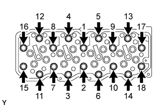
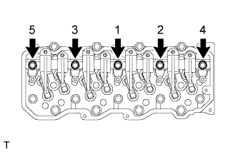
Step 1:
Uniformly install and tighten the cylinder head bolts in the order shown in the illustration.
- Torque:
- 60 N*m { 612 kgf*cm, 44 ft.*lbf }
-
Step 2:
-
Mark the front side of each cylinder head bolt head with paint.
-
Tighten the cylinder head bolts 90°.
-
-
Step 3:
-
Tighten the cylinder head bolts an additional 90°.
-
Check that the paint marks are now at a 180° angle to the front.
-
-
Uniformly install and tighten the cylinder head bolts in the order shown in the illustration.
- Torque:
- 55 N*m { 561 kgf*cm, 41 ft.*lbf }
-
-
INSTALL VALVE BRIDGE
Tech Tips
Be sure to install the removed valve bridges to their original positions.
-
INSTALL VALVE PUSH ROD
Tech Tips
Be sure to install the removed push rods to their original positions.
-
INSTALL NO. 1 VALVE ROCKER SHAFT SUB-ASSEMBLY
-
Lubricate the No. 1 valve rocker shaft sub-assembly and valve rocker arm bush.
Note
Confirm that the oil hole of the No. 1 valve rocker support aligns with the No. 1 valve rocker shaft sub-assembly oil hole. Improper installation will result in burning of the valve.
-
Install the No. 1 valve rocker arms and No. 2 valve rocker arms, No. 1 valve rocker supports and No. 2 valve rocker supports, and the valve rocker arm bushes to the No. 1 valve rocker shaft sub-assembly.
Note
When installing, face the hole on the cylinder head side of the No. 1 valve rocker shaft sub-assembly as shown in the illustration.
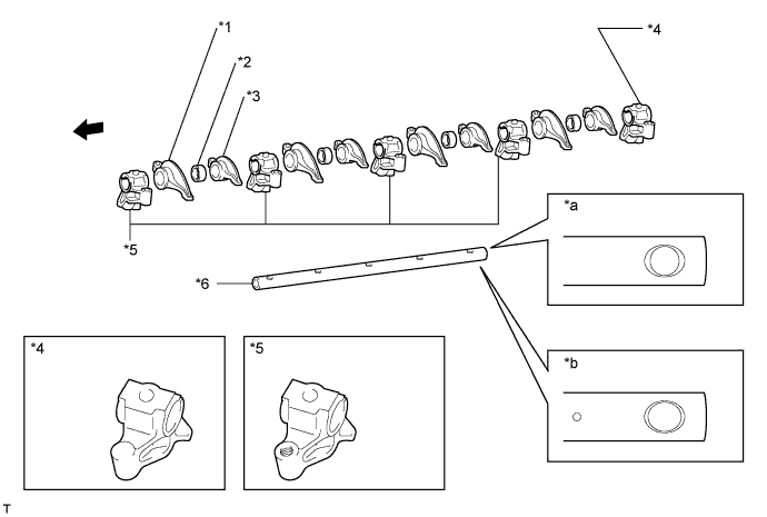
Text in Illustration *1 No. 1 Valve Rocker Arm Sub-assembly *2 Valve Rocker Arm Bush *3 No. 2 Valve Rocker Arm Sub-assembly *4 No. 1 Valve Rocker Support *5 No. 2 Valve Rocker Support *6 No. 1 Valve Rocker Shaft Sub-assembly *a Cylinder Head Cover Side *b Cylinder Head Side 
Front - - -
Apply engine oil to the valve rocker arms and valve push rods.
-
Install the No. 1 valve rocker shaft sub-assembly to the cylinder head sub-assembly.
-
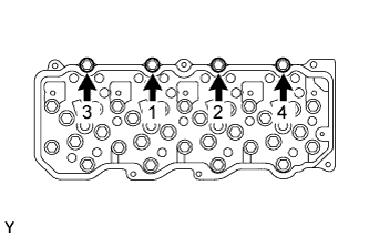
Install the 5 bolts in the order shown in the illustration.
- Torque:
- 69 N*m { 699 kgf*cm, 51 ft.*lbf }
Note
Be careful that the valve push rods do not interfere with the valve adjusting screws.
-
-
ADJUST VALVE CLEARANCE
-
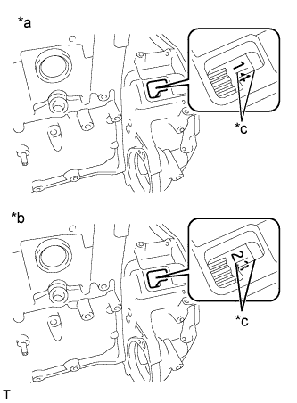
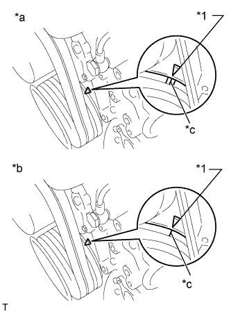
Text in Illustration *a TDC of No. 1 and No. 4 Cylinder *b TDC of No. 2 and No. 3 Cylinder *c Alignment Mark Flywheel housing side:
Turn the crankshaft clockwise to align the alignment mark on the flywheel sub-assembly with the alignment mark between the 2 numbers on the edge of the flywheel housing.
-
Text in Illustration *1 Pointer *a TDC of No. 1 and No. 4 Cylinder *b TDC of No. 2 and No. 3 Cylinder *c Timing Mark Crankshaft pulley side:
Turn the crankshaft clockwise to align the alignment mark on the crankshaft pulley with the pointer on the timing gear case.
Tech Tips
If not, turn the crankshaft 1 revolution (360°) to align the timing mark with the pointer.
-
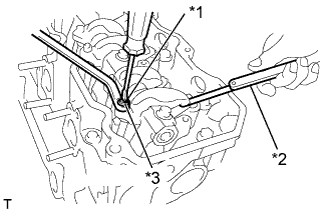
Text in Illustration *1 Adjusting Screw *2 Feeler Gauge *3 Lock Nut With the No. 1 piston positioned at TDC on the compression stroke, adjust each valve clearance using a feeler gauge.
Standard Valve Clearance (Cold) Item Specified Condition Intake 0.25 to 0.40 mm (0.00984 to 0.0157 in.) Exhaust 0.40 to 0.55 mm (0.0157 to 0.0217 in.) Tech Tips
The feeler gauge should move with a very slight pull.
-
Loosen the lock nut on the valve rocker arm and loosen the adjusting screw.
-
Insert a 0.30 mm (0.0118 in.) feeler gauge for the intake or a 0.45 mm (0.0177 in.) feeler gauge for the exhaust between the adjusting screw on the valve rocker arm and the valve bridge.
-
Turn the adjusting screw on the valve rocker arm until the feeler gauge slides with a very slight drag, and lock the adjusting screw with the lock nut.
- Torque:
- 29 N*m { 291 kgf*cm, 21 ft.*lbf }
-
Recheck the clearance.
-
Adjust the other valves.
-
Turn the crankshaft 1 revolution (360°) clockwise.
-
Adjust the valve clearance for each cylinder in the firing order.
Firing order 1 - 3 - 4 - 2 (The cylinder number is counted from the timing gear side)
-
-