ENGINE UNIT DISASSEMBLY

-
SET NO. 1 CYLINDER TO TDC/COMPRESSION
-
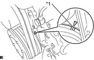
Text in Illustration *1 Timing Mark Set the No. 1 cylinder to TDC/compression.
Tech Tips
-
Make sure that there is free play in the No. 1 cylinder valve rocker arms and that there is no free play in the No. 4 cylinder valve rocker arms.
-
If not, turn the crankshaft 1 revolution (360°) to set the No. 1 cylinder to TDC/compression.
-
-
-
REMOVE NO. 1 VALVE ROCKER SHAFT SUB-ASSEMBLY
-
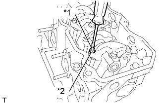
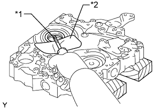
Text in Illustration *1 Valve Adjusting Screw *2 Lock Nut Loosen the lock nuts at the top of the valve rocker arms and completely loosen the valve adjusting screws.
Note
If the valve adjusting screws are not loosened, the No. 1 valve rocker shaft sub-assembly may bend when the valve rocker arm support bolts are loosened.
-
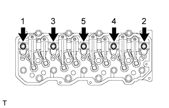
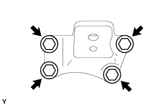
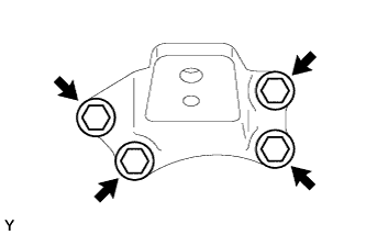
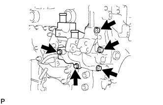
Loosen the valve rocker arm support bolts in the order shown in the illustration.
-
Remove the 5 bolts and No. 1 valve rocker shaft sub-assembly.
-
Remove the No. 1 valve rocker support and No. 2 valve rocker support, No. 1 valve rocker arm and No. 2 valve rocker arm, and the valve rocker arm bushes from the No. 1 valve rocker shaft sub-assembly.
-
-
REMOVE VALVE PUSH ROD
Tech Tips
Organize the parts so that each part location can be remembered for reassembly.
-
REMOVE VALVE BRIDGE
Tech Tips
Organize the parts so that each part location can be remembered for reassembly.
-
REMOVE CYLINDER HEAD SUB-ASSEMBLY
-
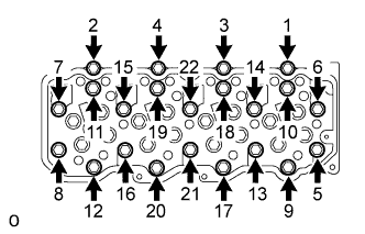
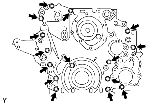
Loosen the cylinder head bolts in the order shown in the illustration and remove the bolts.
-
Lift and remove the cylinder head sub-assembly from the cylinder block.
-
-
REMOVE CYLINDER HEAD GASKET
-
Remove the cylinder head gasket.
-
-
REMOVE VALVE LIFTER
Note
Organize the parts so that each part location can be remembered for reassembly.
-
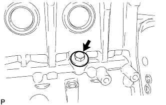
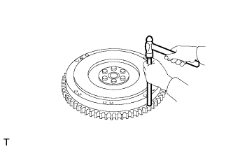
REMOVE CRANKSHAFT PULLEY
-
Using a 46 mm socket wrench, remove the nut, spacer and crankshaft pulley.
Tech Tips
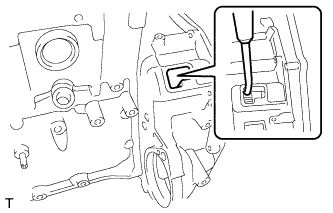
Insert a screwdriver through the inspection hole of the flywheel housing into the ring gear of the flywheel sub-assembly to prevent the ring gear from turning together with the crankshaft.
-
-
REMOVE FLYWHEEL HOUSING STAY LH
-
Remove the 4 bolts and flywheel housing stay LH.
-
-
REMOVE FLYWHEEL HOUSING STAY RH
-
Remove the 4 bolts and flywheel housing stay RH.
-
-
REMOVE FRONT NO. 1 ENGINE MOUNTING BRACKET RH
-
Remove the 4 bolts and front No. 1 engine mounting bracket RH.
-
-
REMOVE FRONT NO. 1 ENGINE MOUNTING BRACKET LH
-
Remove the 4 bolts and front No. 1 engine mounting bracket LH.
-
-
REMOVE OIL PAN SUB-ASSEMBLY
-
Remove the 26 bolts.
-
Insert the blade of an oil pan seal cutter between the crankcase and oil pan sub-assembly. Cut through the applied sealer and remove the oil pan sub-assembly.
Note
Do not damage the contact surfaces of the cylinder block or oil pan sub-assembly.
-
-
REMOVE OIL STRAINER SUB-ASSEMBLY
-
Remove the 3 bolts and oil strainer sub-assembly.
-
Remove the O-ring.
-
-
REMOVE OIL SEPARATOR ASSEMBLY
-
Remove the 5 bolts and oil separator from the timing gear case.
-
Remove the 3 O-rings.
-
-
REMOVE TIMING GEAR CASE
-
Remove the 15 bolts.
-
Using a screwdriver with its tip wrapped in protective tape, pry out the timing gear case.
Note
Do not damage the contact surfaces of the timing gear case or cylinder block.
-
-
REMOVE TIMING CHAIN OR BELT COVER OIL SEAL
-
Text in Illustration *1 Protective Tape *2 Cloth Using a screwdriver with its tip wrapped in protective tape, pry out the timing chain or belt cover oil seal.
Tech Tips
Use a cloth to prevent damage to the timing gear case.
-
-
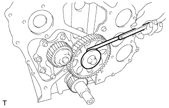
INSPECT NO. 2 IDLE GEAR THRUST CLEARANCE
-

Using a feeler gauge, measure the thrust clearance between the No. 2 idle gear thrust plate and No. 2 idle gear sub-assembly.
Standard thrust clearance 0.103 to 0.164 mm (0.00406 to 0.00646 in.) Maximum thrust clearance 0.30 mm (0.0118 in.) If the thrust clearance is more than the maximum, replace the No. 2 idle gear thrust plate and No. 2 idle gear sub-assembly.
-
-
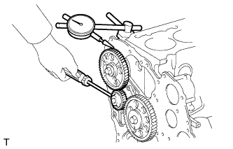
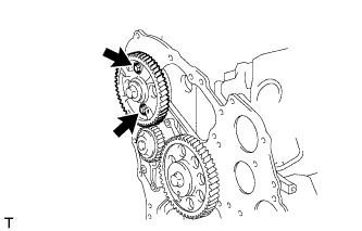
INSPECT NO. 2 IDLE GEAR BACKLASH
-
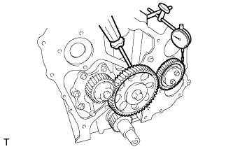
Using a dial indicator, measure the backlash between the No. 1 idle gear sub-assembly and No. 2 idle gear sub-assembly.
Standard backlash 0.036 to 0.166 mm (0.00142 to 0.00654 in.) Maximum backlash 0.30 mm (0.0118 in.) If the backlash is more than the maximum, replace the No. 1 idle gear sub-assembly and No. 2 idle gear sub-assembly.
-
-
REMOVE NO. 2 IDLE GEAR THRUST PLATE
-
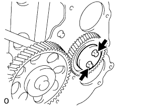
Remove the 2 bolts and No. 2 idle gear thrust plate.
-
-
REMOVE NO. 2 IDLE GEAR SUB-ASSEMBLY
-
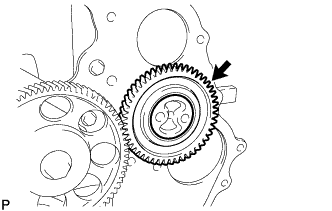
Remove the No. 2 idle gear sub-assembly from the No. 2 idle gear shaft.
-
-
REMOVE NO. 2 IDLE GEAR SHAFT
-
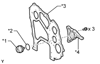
Text in Illustration *1 No. 2 Idle Gear Shaft *2 O-Ring *3 Front End Plate *4 Lock Plate Remove the 3 bolts, No. 2 idle gear shaft and lock plate.
-
Remove the O-ring from the No. 2 idle gear shaft.
-
-
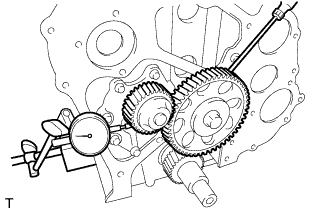
INSPECT CAMSHAFT TIMING GEAR BACKLASH
-
Using a dial indicator, measure the backlash between the camshaft timing gear and No. 1 idle gear sub-assembly.
Standard backlash 0.068 to 0.171 mm (0.00268 to 0.00673 in.) Maximum backlash 0.30 mm (0.0118 in.) If the backlash is more than the maximum, replace the camshaft timing gear and No. 1 idle gear sub-assembly.
-
-
REMOVE CAMSHAFT
-
Remove the 2 bolts and camshaft.
-
-
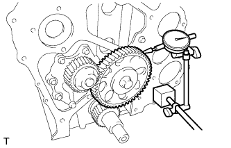
INSPECT OIL PUMP GEAR BACKLASH
-
Using a dial indicator, measure the backlash between the oil pump gear and No. 1 idle gear sub-assembly.
Standard backlash 0.065 to 0.178 mm (0.00256 to 0.00701 in.) Maximum backlash 0.30 mm (0.0118 in.) If the backlash is more than the maximum, replace the oil pump assembly and No. 1 idle gear sub-assembly.
-
-
INSPECT NO. 1 IDLE GEAR THRUST CLEARANCE
-
Using a feeler gauge, measure the thrust clearance between the No. 1 idle gear thrust plate and No. 1 idle gear sub-assembly.
Standard thrust clearance 0.103 to 0.164 mm (0.00406 to 0.00646 in.) Maximum thrust clearance 0.30 mm (0.0118 in.) If the thrust clearance is more than the maximum, replace the No. 1 idle gear thrust plate and No. 1 idle gear sub-assembly.
-
-
INSPECT NO. 1 IDLE GEAR BACKLASH
-
Using a dial indicator, measure the backlash between the crankshaft timing gear and No. 1 idle gear sub-assembly.
Standard backlash 0.035 to 0.162 mm (0.00138 to 0.00638 in.) Maximum backlash 0.30 mm (0.0118 in.) If the backlash is more than the maximum, replace the crankshaft timing gear or sprocket and No. 1 idle gear sub-assembly.
-
-
REMOVE NO. 1 IDLE GEAR SHAFT
-
Remove the bolt.
-

Using SST, remove the No. 1 idle gear shaft.
- SST
- 09910-00015 ( 09911-00011, 09912-00010 )
Note
When removing the No. 1 idle gear shaft, hold the No. 1 idle gear sub-assembly by hand to prevent the No. 1 idle gear sub-assembly and No. 1 idle gear thrust plate from falling.
-
-
REMOVE NO. 1 IDLE GEAR SUB-ASSEMBLY
-
REMOVE NO. 1 IDLE GEAR THRUST PLATE
-
REMOVE CRANKSHAFT TIMING GEAR OR SPROCKET
-

Text in Illustration *a Hold *b Turn Clockwise Using SST, remove the crankshaft timing gear or sprocket.
- SST
- 09950-40011 ( 09951-04010, 09952-04010, 09953-04020, 09954-04010, 09955-04051 )
-
-
REMOVE OIL PUMP ASSEMBLY
-
Remove the 7 bolts, oil pump assembly and gasket.
-
-
REMOVE FRONT END PLATE
-
Remove the 4 bolts, front end plate and gasket.
-
-
REMOVE OIL CHECK VALVE SUB-ASSEMBLY
-
Remove the oil check valve sub-assembly and gasket.
-
-
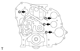
REMOVE FLYWHEEL HOUSING
-

Temporarily install the 4 bolts in the positions on the cylinder block shown in the illustration to prevent the cables from sliding toward the center of the cylinder block.
-
Attach the 2 cables to the cylinder block.
Tech Tips
The cables must be attached outside the installed bolts.
-
Using a chain block and engine sling device, remove the cylinder block from the engine stand.
-
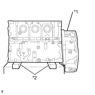
Text in Illustration *1 Flywheel Housing *2 Wooden Block Place the cylinder block on wooden blocks on a workbench.
-
Remove the 4 bolts from the cylinder block.
-
Remove the 14 bolts from the cylinder block.
-
Using a screwdriver with its tip wrapped with protective tape, pry off the flywheel housing.
-
-
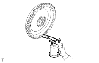
REMOVE REAR ENGINE OIL SEAL
-

Text in Illustration *1 Protective Tape *2 Wooden Block *3 Cloth Using a screwdriver with its tip wrapped with protective tape, pry out the rear engine oil seal.
Tech Tips
Use wooden blocks and a cloth to prevent damage to the flywheel housing.
-
-
REMOVE FLYWHEEL RING GEAR
-
Using a torch, heat the flywheel ring gear evenly to approximately 200°C (392°F).
CAUTION:
Do not touch the flywheel ring gear and flywheel sub-assembly while they are hot.
Note
Be careful not to overheat the flywheel ring gear.
-
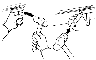
Using a brass bar and hammer, uniformly strike around the circumference of the flywheel ring gear and remove the flywheel gear.
CAUTION:
After removing the ring gear, allow the flywheel ring gear to cool before handling it.
-