ENGINE ASSEMBLY INSTALLATION

-
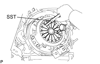
INSTALL ENGINE HANGER
-
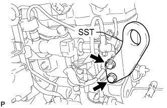
Install SST with bolts to the position shown in the illustration.
- SST
- S1220-31210
- Torque:
- 125 N*m { 1275 kgf*cm, 92 ft.*lbf }
Tech Tips
Use the following specified bolts with spring washers;
Item Specified Condition Thread Diameter 12 mm (0.472 in.) Pitch 1.75 mm (0.0689 in.) Strength Grade 9T Length 35 mm (1.38 in.)
-
-
REMOVE ENGINE STAND
-
Attach an engine sling device and hang the engine with a chain block.
-
Lift the engine assembly and remove it from the engine stand.
CAUTION:
With the exception of installing the engine assembly to an engine stand or removing the engine assembly from an engine stand, do not perform any work on the engine while it is suspended, as doing so is dangerous.
Note
Pay attention to the angle of the sling device as the engine assembly or engine hangers may be damaged or deformed if the angle is incorrect.
-
-
REMOVE FLYWHEEL SUB-ASSEMBLY
-
Insert the flywheel sub-assembly slowly until it contacts the collar knock in order to prevent impact to the guide bar. Adjust the position of the flywheel and insert it completely.
-
Apply a light coat of engine oil to the threads of the flywheel set bolts and flywheel set bolt seats.
-
Temporarily install the flywheel sub-assembly with the flywheel set bolts.
-
Step 1:
-
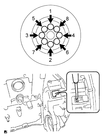
Install the flywheel set bolts in the order shown in the illustration.
- Torque:
- 86 N*m { 877 kgf*cm, 63 ft.*lbf }
Tech Tips
Insert a screwdriver through the inspection hole of the flywheel housing into the ring gear of the flywheel sub-assembly to prevent the ring gear from turning together with the crankshaft.
-
-
Step 2:
-
Mark the top of each flywheel sub-assembly bolt head with paint.
-
Tighten the bolts 45° in the order shown in the illustration.
-
Check that the paint marks are now at a 45° angle to the top.
-
-
-
INSTALL ENGINE ASSEMBLY
-
Install the engine assembly to the 2 engine mounting brackets with the 2 nuts.
- Torque:
- 98 N*m { 999 kgf*cm, 72 ft.*lbf }
Note
-
Make sure that the engine assembly is clear of all wiring and hoses
-
While lowering the engine assembly into the vehicle, do not allow it to contact the vehicle.
-
Support the engine assembly.
-
-
INSTALL CLUTCH DISC ASSEMBLY
-
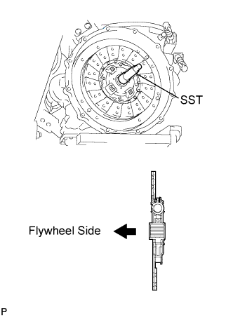
Insert SST into the clutch disc assembly, then insert them into the flywheel sub-assembly.
- SST
- 09301-00120
Note
Take care not to insert the clutch disc assembly in the wrong direction.
-
-
INSTALL CLUTCH COVER ASSEMBLY
-
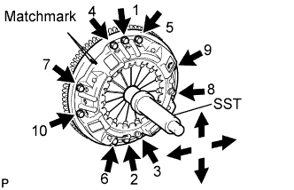
Align the matchmark on the clutch cover assembly with the one on the flywheel sub-assembly.
-
In the order shown in the illustration, tighten the 10 bolts starting from the bolt located near the knock pin on the top.
- Torque:
- 43 N*m { 440 kgf*cm, 32 ft.*lbf }
Tech Tips
-
Evenly tighten the bolts by following the order shown in the illustration.
-
Tighten the bolts after checking that the disc is in the center by lightly moving SST up and down, left and right.
- SST
- 09301-00120
-
-
INSPECT AND ADJUST CLUTCH COVER ASSEMBLY
-
Using a dial indicator with a roller instrument, check the diaphragm spring tip alignment.
Maximum misalignment 0.5 mm (0.020 in.) -
If alignment is not as specified, adjust the diaphragm spring tip alignment using SST.
- SST
- 09333-00013
-
-
INSTALL MANUAL TRANSMISSION ASSEMBLY
-
INSTALL PROPELLER INTERMEDIATE SHAFT ASSEMBLY
-
REMOVE ENGINE HANGER
-
Detach an engine sling device and remove the 2 bolts and engine hanger.
-
-
INSTALL EGR COOLER SUB-ASSEMBLY
-
CONNECT WIRE HARNESS
-
CONNECT FUEL HOSE
-
Connect the No. 2 fuel hose to the No. 2 fuel return pipe, and slide the clamp to secure the hose.
-
Connect the No. 1 fuel hose to the No. 1 fuel pipe, and slide the clamp to secure the hose.
-
-
INSTALL NO. 1 HOSE SUPPORT BRACKET
-
Install the No. 1 hose support bracket with the 3 bolts.
- Torque:
- 29 N*m { 291 kgf*cm, 21 ft.*lbf }
-
Install the nut to the oil pump to gear box tube.
- Torque:
- 44 N*m { 449 kgf*cm, 32 ft.*lbf }
-
-
CONNECT NO. 2 OIL RESERVOIR TO PUMP HOSE
-
Connect the No. 2 oil reservoir to pump hose to the power steering suction port union, and slide the clamp to secure the hose.
-
-
CONNECT PRESSURE FEED HOSE
-
Connect the pressure feed hose to the oil pump gear box tube.
- Torque:
- 44 N*m { 449 kgf*cm, 32 ft.*lbf }
Note
Use the formula to calculate special torque values for situations where a union nut wrench is combined with a torque wrench Click here.
-
-
INSTALL EXHAUST RETARDER ASSEMBLY
-
Install the exhaust retarder assembly to the turbocharger sub-assembly.
-
Connect the vacuum hose to the exhaust retarder assembly.
-
-
INSTALL FRONT EXHAUST PIPE ASSEMBLY
-
INSTALL STARTER ASSEMBLY
-
INSTALL GENERATOR ASSEMBLY
-
CONNECT COOLER COMPRESSOR ASSEMBLY
-
Connect the cooler compressor assembly with the 4 bolts.
- Torque:
- 25 N*m { 250 kgf*cm, 18 ft.*lbf }
-
Connect the connector.
-
Connect the cooler pipe with the bolt.
- Torque:
- 19 N*m { 194 kgf*cm, 14 ft.*lbf }
-
-
INSTALL RADIATOR ASSEMBLY
-
CONNECT NO. 2 RADIATOR HOSE
-
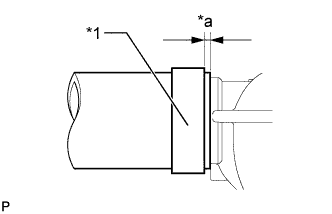
Text in Illustration *1 Hose Clamp *a 10.0 mm (0.394 in.) or less Securely push the outlet radiator hose onto the radiator assembly until it contacts the stopper, and then install the hose clamp in the location shown in the illustration.
-
-
CONNECT NO. 1 RADIATOR HOSE
-
Text in Illustration *1 Hose Clamp *a 10.0 mm (0.394 in.) or less Securely push the inlet radiator hose onto the radiator assembly until it contacts the stopper, and then install the hose clamp in the location shown in the illustration.
-
-
INSTALL NO. 1 V (COOLER COMPRESSOR TO CRANKSHAFT PULLEY) BELT
-
Install the No. 1 V (cooler compressor to crankshaft pulley) belt.
-
-
ADJUST NO. 1 V (COOLER COMPRESSOR TO CRANKSHAFT PULLEY) BELT
-
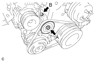
Turn bolt B to adjust the tension of the No. 1 V (cooler compressor to crankshaft pulley) belt.
-
Tighten bolt A.
- Torque:
- 44 N*m { 449 kgf*cm, 32 ft.*lbf }
-
Tighten bolt B.
- Torque:
- 6.0 N*m { 61 kgf*cm, 53 in.*lbf }
-
Check that the V belt fits properly into the grooves.
Tech Tips
Confirm by hand that the No. 1 V (cooler compressor to crankshaft pulley) belt has not slipped out of the grooves on the bottom of the pulley.
-
-
INSTALL FAN PULLEY
-
Install the fan pulley to the engine water pump assembly.
-
-
INSTALL FAN
-
Temporarily install the fan with the 4 nuts.
-
Install the fan and generator V belt Click here.
-
Tighten the 4 nuts.
- Torque:
- 29 N*m { 291 kgf*cm, 21 ft.*lbf }
-
-
INSTALL REAR CAB MOUNTING BRACKET SUB-ASSEMBLY
-
Install the rear cab mounting bracket sub-assembly with the 4 bolts.
- Torque:
- 86 N*m { 877 kgf*cm, 63 ft.*lbf }
-
-
INSTALL REAR ENGINE SIDE SHUTTER
-
Install the rear engine side shutter to the rear cab mounting bracket sub-assembly with the 4 bolts.
- Torque:
- 13 N*m { 133 kgf*cm, 10 ft.*lbf }
-
-
INSTALL RELAY BLOCK BRACKET SUB-ASSEMBLY
-
Install the relay block bracket sub-assembly with the 2 bolts and 2 nuts.
- Torque:
- 29 N*m { 296 kgf*cm, 21 ft.*lbf }
-
-
CONNECT RELAY BLOCK
-
Connect the relay block with the 2 bolts and nut.
- Torque:
- 29 N*m { 296 kgf*cm, 21 ft.*lbf }
-
-
INSTALL INJECTOR DRIVER ASSEMBLY
-
Install the injector driver assembly with the 2 bolts.
- Torque:
- 31 N*m { 316 kgf*cm, 23 ft.*lbf }
-
Connect the 3 injector driver assembly connectors.
-
-
INSTALL STARTER RELAY ASSEMBLY
-
Install the starter relay assembly with the 2 nuts.
- Torque:
- 8.0 N*m { 82 kgf*cm, 71 in.*lbf }
-
Connect the connector and attach the wire harness clamp.
-
Connect the 2 lead wires to the starter relay assembly with the 2 nuts.
- Torque:
- 4.7 N*m { 48 kgf*cm, 42 in.*lbf }
-
Install the terminal cap.
-
-
INSTALL EXHAUST BRAKE WITH BRACKET SOLENOID ASSEMBLY
-
Install the exhaust brake solenoid with bracket assembly with the 2 bolts.
- Torque:
- 31 N*m { 316 kgf*cm, 23 ft.*lbf }
-
Connect the exhaust retarder hose and solenoid hose with the 2 clips.
-
Connect the connector to the exhaust brake solenoid with bracket assembly.
-
-
INSTALL AIR CLEANER ASSEMBLY
-
Install the air cleaner assembly to the No. 1 air cleaner stay with the 4 nuts
- Torque:
- 18 N*m { 184 kgf*cm, 13 ft.*lbf }
-
-
INSTALL AIR CLEANER STAY
-
Install the No. 1 air cleaner stay and No. 2 air cleaner stay with the 3 nuts.
- Torque:
- 31 N*m { 316 kgf*cm, 23 ft.*lbf }
-
-
INSTALL AIR HOSE ASSEMBLY
-
Install 2 new hose clamps to the air hose assembly.
-
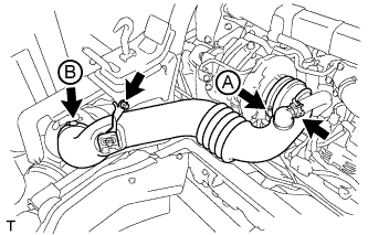
Install the air hose assembly with the bolt.
- Torque:
- 20 N*m { 199 kgf*cm, 14 ft.*lbf }
-
Tighten the 2 hose clamps.
- Torque:
- for hose clamp A
- 6.3 N*m { 64 kgf*cm, 56 in.*lbf }
- for hose clamp B
- 3.7 N*m { 38 kgf*cm, 33 in.*lbf }
-
Install the ventilation hose to the air hose assembly, and slide the clamp to secure the hose.
-
-
INSTALL FENDER SIDE APRON SUB-ASSEMBLY LH
-
Install the fender side apron sub-assembly LH with the 6 bolts.
- Torque:
- 12 N*m { 117 kgf*cm, 8 ft.*lbf }
-
-
INSTALL FENDER SIDE APRON SUB-ASSEMBLY RH
-
Install the fender side apron sub-assembly RH with the 6 bolts.
- Torque:
- 12 N*m { 117 kgf*cm, 8 ft.*lbf }
-
-
INSTALL ENGINE SIDE COVER SUB-ASSEMBLY LH
-
Install the engine side cover sub-assembly LH with the 4 bolts.
- Torque:
- 12 N*m { 117 kgf*cm, 8 ft.*lbf }
-
-
INSTALL ENGINE SIDE COVER SUB-ASSEMBLY RH
-
Install the engine side cover sub-assembly RH with the 4 bolts.
- Torque:
- 12 N*m { 117 kgf*cm, 8 ft.*lbf }
-
-
CONNECT CABLE TO NEGATIVE BATTERY TERMINAL
Note
When disconnecting the cable, some systems need to be initialized after the cable is reconnected Click here.
-
CHECK INJECTOR COMPENSATION CODE
-
ADD ENGINE OIL
-
Add new engine oil.
Standard Oil Grade Oil Grade Oil Viscosity (SAE) API (CJ-4)
JASO (DH-2)
ACEA (E-6, E-9)
- 5W-30
- 10W-30
- 15W-40
Standard Capacity Item Specified Condition Drain and refill without oil filter change 5.2 liters (5.5 US qts, 4.6 Imp. qts) Drain and refill with oil filter change 6.5 liters (6.9 US qts, 5.7 Imp. qts) Dry fill 8.7 liters (9.2 US qts, 7.7 Imp. qts) -
Install the oil filler cap.
-
-
ADD ENGINE COOLANT
CAUTION:
Do not remove the radiator cap sub-assembly, radiator drain cock plug or engine drain plug while the engine and radiator are still hot. Pressurized, hot engine coolant and steam may be released and cause serious burns.
Note
Do not substitute plain water for engine coolant.
-
Add engine coolant.
Standard capacity 14.2 liters (15.0 US qts, 12.5 Imp. qts) Tech Tips
TOYOTA vehicles are filled with TOYOTA SLLC at the factory. In order to avoid damage to the engine cooling system and other technical problems, only use TOYOTA SLLC or similar high quality ethylene glycol based non-silicate, non-amine, non-nitrite, non-borate coolant with long-life hybrid organic acid technology (coolant with long-life hybrid organic acid technology is a combination of low phosphates and organic acids).
-
Check the coolant level inside the radiator by squeezing the inlet radiator hose and outlet radiator hose several times by hand. If the coolant level goes down, add coolant.
-
Install the radiator cap sub-assembly.
-
Slowly pour coolant into the radiator reservoir until it reaches the F line.
-
Bleed air from the cooling system.
-
Warm up the engine until the thermostat opens.
While the thermostat is open, circulate the coolant for several minutes.
-
Maintain the engine speed at a speed between 2500 and 3000 rpm.
-
Press the inlet and outlet radiator hoses several times by hand to bleed air.
Note
-
Wear protective gloves.
-
Be careful as the radiator hoses are hot.
-
Keep your hands away from the radiator fan.
-
-
-
Stop the engine and wait until the coolant cools down to ambient temperature.
-
Remove the radiator cap sub-assembly and check the coolant level.
If the coolant level has dropped, add coolant.
-
Check the coolant level inside the radiator reservoir assembly again.
If the coolant level is below the F line, add coolant to F line.
-
-
ADD POWER STEERING FLUID
-
BLEED AIR FROM FUEL SYSTEM
-
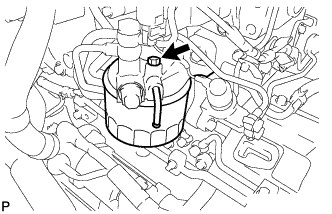
Loosen the bleeder plug.
Text in Illustration 
Bleeder Plug Note
Make sure that the drain plug and bleeder plug of the filter on the fuel tank side are closed.
-
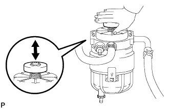
Bleed air using the priming pump on the fuel tank side.
Note
-
Place a container, etc. underneath the fuel filter to prevent fuel from spraying.
-
The hand pump must be pushed with a full stroke during pumping.
-
The maximum hand pump pumping speed is 2 strokes per second.
-
When the fuel pressure at the supply pump inlet port reaches a saturated pressure, the hand pump resistance increases.
-
If pumping is interrupted during the air bleeding process, fuel in the fuel line may return to the fuel tank. Continue pumping until the hand pump resistance increases.
-
If the hand pump resistance does not increase despite consecutively pumping 200 times or more, there may be a fuel leak between the fuel tank and fuel filter, the hand pump may be malfunctioning, or the vehicle may have run out of fuel.
-
If air bleeding using the hand pump is incomplete, the common rail pressure does not rise to the pressure range necessary for normal use and the engine cannot be started.
-
-
Tighten the bleeder plug.
- Torque:
- 6.9 N*m { 70 kgf*cm, 61 in.*lbf }
-
Check if the engine starts.
Note
-
Even if air bleeding using the hand pump has been completed, the starter may need to be cranked for 10 seconds or more to start the engine.
-
Do not crank the engine continuously for more than 20 seconds. The battery may be discharged.
-
Use a fully-charged battery.
-
When the engine can be started, proceed to the next step.
Tech Tips
If the engine cannot be started, bleed air again using the hand pump until the hand pump resistance increases (refer to the procedures above). Then start the engine.
-
-
Turn the ignition switch off.
-
Connect the intelligent tester to the DLC3.
-
Turn the ignition switch to ON and turn the intelligent tester on.
-
Clear the DTCs Click here.
-
Start the engine.*1
-
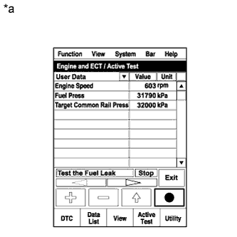
Text in Illustration *a Reference
(Active Test operation)
Enter the following menus: Powertrain / Engine and ECT / Active Test / Test the Fuel Leak.*2
-
Perform the following test 5 times with on/off intervals of 10 seconds: Active Test / Test the Fuel Leak.*3
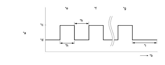
Text in Illustration *a Active Test operation *b Time *c ON *d OFF *e 1st time *f 2nd time *g 5th time *h 10 seconds *i 3 minutes or more - - -
Allow the engine to idle for 3 minutes or more after performing the Active Test for the 5th time.
-
Enter the following menus: Powertrain / Engine and ECT / DTC.
-
Read Current DTCs.
-
If no DTCs are output, air bleeding is completed.
-
If DTCs are output, perform the following procedure.
-
-
Clear the DTCs Click here.
-
Repeat steps *1 to *3.
-
Enter the following menus: Powertrain / Engine and ECT / DTC.
-
Read Current DTCs.
OK No DTCs are output
-
-
INSPECT FOR COOLANT LEAK
CAUTION:
Do not remove the radiator cap while the engine and radiator are still hot. Pressurized, hot engine coolant and steam may be released and cause serious burns.
Note
Before each inspection, turn the A/C switch off.
-
Fill the radiator with coolant and attach a radiator cap tester.
-
Warm up the engine.
-
Using the radiator cap tester, increase the pressure inside the radiator to 137 kPa (1.4 kgf/cm2, 20 psi), and check that the pressure does not drop.
If the pressure drops, check the hoses, radiator assembly and engine water pump for leaks. If no external leaks are found, check the heater core, cylinder block and cylinder head.
-
-
INSPECT OIL LEAK
-
Start the engine. Make sure that there are no oil leaks from the areas that were worked on.
-
-
BLEED AIR FROM POWER STEERING SYSTEM
-
Check the fluid level Click here.
-
Jack up the front of the vehicle and support it with stands.
-
Turn the steering wheel.
-
With the engine stopped, turn the steering wheel slowly from lock to lock several times.
-
-
Lower the vehicle.
-
Start the engine.
-
Run the engine at idle for a few minutes.
-
-
Turn the steering wheel.
-
With the engine idling, turn the steering wheel left or right to the full lock position and keep it in that position for 2 to 3 seconds, then turn the steering wheel to the opposite full lock position and keep it there for 2 to 3 seconds (*1).
-
Repeat this procedure (*1) several times.
-
-
Stop the engine.
-
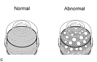
Check for foaming or emulsification.
Tech Tips
If the system has to be bled twice because of forming or emulsification, be sure to check for fluid leaks in the system.
-
Check the fluid level Click here.
-
-
CHECK POWER STEERING FLUID LEVEL
-
Keep the vehicle level.
-
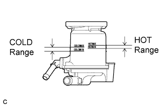
With the engine stopped, check the fluid level in the fluid reservoir.
If necessary, add fluid.
Fluid ATF DEXRON II or III, or equivalent. Tech Tips
If the fluid is hot, check that the fluid level is within the HOT range on the fluid reservoir. If the fluid is cold, check that the fluid level is within the COLD range.
-
Start the engine and run it at idle.
-
Turn the steering wheel from lock to lock several times to raise fluid temperature.
Fluid temperature 50 to 60°C (122 to 140°F) -
Check for foaming or emulsification.
If foaming or emulsification is identified, bleed the power steering system Click here.
-
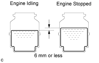
With the engine idling, measure the fluid level in the fluid reservoir.
-
Stop the engine.
-
Wait a few minutes and remeasure the fluid level in the fluid reservoir.
Maximum fluid level rise 6 mm (0.24 in.) If any problem is found, bleed the power steering system Click here.
-
Check the fluid level.
-
-
INSPECT FOR EXHAUST GAS LEAK
-
If gas is leaking, tighten the areas necessary to stop the leak. Replace damaged parts as necessary.
-
-
INSPECT FOR FUEL LEAK
-
Perform the Active Test.
-
Replace the normal DLC3 cable (12 V specification) for the intelligent tester with the 24 V DLC3 cable.
Note
Be sure to use the 24 V DLC3 cable when connecting the intelligent tester to the DLC3. Using the normal DLC3 cable (12 V specification) will cause damage to the tester.
-
Connect the intelligent tester to the DLC3.
-
Start the engine.
-
Turn the intelligent tester on.
-
Enter the following menus: Powertrain / Engine and ECT / Active Test.
-
Perform the Active Test.
Tester Display Test Part Control Range Diagnostic Note Test the Fuel Leak Pressurizes common rail interior and checks for fuel leaks Stop or Start
-
The fuel pressure inside the common rail is increased to a specified value and the engine speed is increased to 2000 rpm when Start is selected
-
The above conditions are preserved while the control parameter of the test is Start
-
-
-
Check for leaks from the fuel system while performing the Active Test (with a fuel pressure applied).
-
-
INSPECT AND ADJUST MANUAL TRANSMISSION OIL
-
INSPECT DRIVE BELT DEFLECTION AND TENSION (REFERENCE)
-
Check the V belt for wear, cracks or other signs of damage.
If any of the following defects is found, replace the V belt.
-
The V belt is cracked.
-
The V belt is worn out to the extent that the cords are exposed.
-
The V belt has chunks missing from the ribs.
-
-
Check that the V belt fits properly in the ribbed grooves.
Tech Tips
Check with your hand to confirm that the V belt has not slipped out of the groove on the bottom of the pulley. If it has slipped out, replace the V belt. Install the V belt correctly.
-
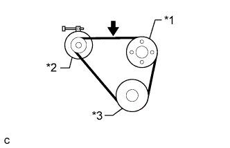
Text in Illustration *1 Fan Pulley *2 Generator *3 Crankshaft Pulley Check the fan and generator V belt deflection.
Standard Deflection Item Specified Condition New belt 10.5 to 12.5 mm (0.413 to 0.492 in.) Used belt 12 to 13 mm (0.472 to 0.512 in.) Note
-
Check the V belt deflection at the specified point.
-
When inspecting a V belt which has been used for over 5 minutes, use the used V belt specifications.
Tech Tips
When inspecting the V belt deflection, apply 98 N (10 kgf, 22 lbf) of tensile force to it.
-
-
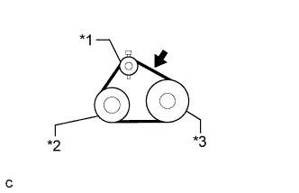
Text in Illustration *1 Idler Pulley *2 A/C Compressor *3 Crankshaft Pulley Check the No. 1 V (cooler compressor to crankshaft pulley) belt deflection.
Standard Deflection Item Specified Condition New belt 7 to 9 mm (0.276 to 0.354 in.) Used belt 8.5 to 10 mm (0.335 to 0.394 in.) Note
-
Check the V belt deflection at the specified point.
-
When inspecting a V belt which has been used for over 5 minutes, use the used V belt specifications.
Tech Tips
When inspecting the V belt deflection, apply 98 N (10 kgf, 22 lbf) of tensile force to it.
-
-
-
INSTALL ENGINE UNDER COVER LH
-
Install the engine under cover LH with the 2 bolts and nut.
- Torque:
- for bolt
- 31 N*m { 316 kgf*cm, 23 ft.*lbf }
- for nut
- 20 N*m { 199 kgf*cm, 14 ft.*lbf }
-
-
INSTALL ENGINE UNDER COVER RH
-
Install the engine under cover RH with the 2 bolts and nut.
- Torque:
- for bolt
- 31 N*m { 316 kgf*cm, 23 ft.*lbf }
- for nut
- 20 N*m { 199 kgf*cm, 14 ft.*lbf }
-
-
INSPECT IDLE SPEED AND MAXIMUM SPEED
Note
Turn all electrical systems and the A/C off.
-
Warm up and stop the engine.
-
Replace the normal DLC3 cable (12 V specification) for the intelligent tester with the 24 V DLC3 cable.
Note
Be sure to use the 24 V DLC3 cable when connecting the intelligent tester to the DLC3. Using the normal DLC3 cable (12 V specification) will cause damage to the tester.
-
Connect the intelligent tester to the DLC3.
-
Turn the ignition switch to ON.
-
Enter the following menus: Powertrain / Engine and ECT / Data List
Tech Tips
Refer to the intelligent tester operator's manual for further information regarding the selection of the Data List.
-
Inspect the engine idle speed.
Standard idle speed 600 to 700 rpm -
Fully depress the accelerator pedal.
-
Check the maximum speed.
Maximum speed 3300 to 3400 rpm -
Turn the ignition switch off.
-
Disconnect the intelligent tester from the DLC3.
-