ENGINE ASSEMBLY REMOVAL

-
TILT UP CAB
CAUTION:
-
Make sure that the vehicle is on a level surface before tilting the cab up.
-
Make sure that all the doors are closed before tilting the cab up.
-
Make sure that nobody is inside or near the cab when tilting it up.
-
Be sure to have 2 people tilt the cab up when a heavy object such as a roof rack or cargo carrier is installed to the cab.
-
Be sure to remove anything set on top of the cab before tilting it up.
-
Make sure that the cab is securely locked in place after it is tilted up.
-
Make sure that there are no tools, cloths, etc. left in the engine room before tilting the cab back down.
-
Make sure that the cab is securely locked in place after tilting it back down.
-
-
CHECK ID CODE
-
PRECAUTION
Note
After turning the ignition switch off, waiting time may be required before disconnecting the cable from the battery terminal. Therefore, make sure to read the disconnecting the cable from the battery terminal notice before proceeding with work Click here.
-
DISCONNECT CABLE FROM NEGATIVE BATTERY TERMINAL
Note
When disconnecting the cable, some systems need to be initialized after the cable is reconnected Click here.
-
REMOVE ENGINE UNDER COVER LH
-
Remove the 2 bolts, nut and engine under cover LH.
-
-
REMOVE ENGINE UNDER COVER RH
-
Remove the 2 bolts, nut and engine under cover RH.
-
-
DRAIN ENGINE OIL
-
Remove the oil filler cap.
-
Remove the oil pan drain plug and gasket, and then drain the engine oil into a container.
-
Wipe the oil pan and oil pan drain plug.
-
Install a new gasket and the oil pan drain plug.
- Torque:
- 41 N*m { 418 kgf*cm, 30 ft.*lbf }
-
-
DRAIN COOLANT
CAUTION:
Do not remove the radiator cap sub-assembly, radiator drain cock plug or engine drain plug while the engine and radiator are still hot. Pressurized, hot engine coolant and steam may be released and cause serious burns.
-
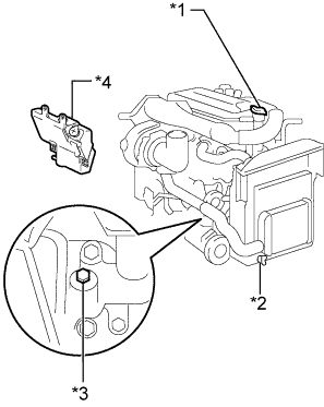
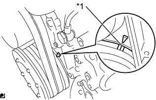
Text in Illustration *1 Radiator Cap Sub-assembly *2 Radiator Drain Cock Plug *3 Engine Drain Plug *4 Radiator Reservoir Assembly Loosen the radiator drain cock plug and engine drain plug.
-
Remove the radiator cap sub-assembly, and then drain the coolant.
Tech Tips
Collect the coolant in a container and dispose of it according to the local regulations.
-
Tighten the radiator drain cock plug by hand.
-
Tighten the engine drain plug.
- Torque:
- 27 N*m { 275 kgf*cm, 20 ft.*lbf }
-
-
DRAIN POWER STEERING FLUID
-
REMOVE ENGINE SIDE COVER SUB-ASSEMBLY LH
-
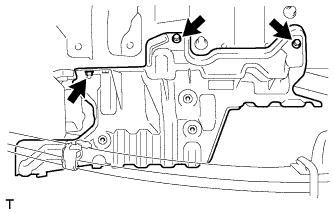
Remove the 4 bolts and engine side cover sub-assembly LH.
-
-
REMOVE ENGINE SIDE COVER SUB-ASSEMBLY RH
-
Remove the 4 bolts and engine side cover sub-assembly RH.
-
-
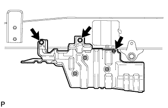
REMOVE FENDER SIDE APRON SUB-ASSEMBLY LH
-
Remove the 6 bolts and fender side apron sub-assembly LH.
-
-
REMOVE FENDER SIDE APRON SUB-ASSEMBLY RH
-
Remove the 6 bolts and fender side apron sub-assembly RH.
-
-
REMOVE AIR HOSE ASSEMBLY
-
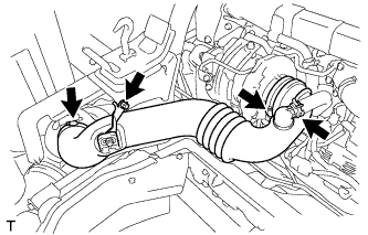
Slide the clamp and disconnect the ventilation hose from the air hose assembly.
-
Loosen the 2 hose clamps.
-
Remove the bolt and air hose assembly.
-
-
REMOVE AIR CLEANER ASSEMBLY
-
Remove the 4 nuts and air cleaner assembly from the No. 1 air cleaner stay.
-
-
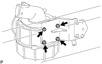
REMOVE AIR CLEANER STAY
-
Remove the 3 nuts, No. 1 air cleaner stay and No. 2 air cleaner stay.
-
-
REMOVE EXHAUST BRAKE WITH BRACKET SOLENOID ASSEMBLY
-
Disconnect the connector from the exhaust brake solenoid with bracket assembly.
-
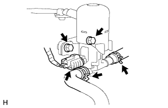
Slide the 2 clips and disconnect the exhaust retarder hose and solenoid hose from the exhaust brake solenoid with bracket assembly.
-
Remove the 2 bolts and exhaust brake solenoid with bracket assembly.
-
-
REMOVE STARTER RELAY ASSEMBLY
-
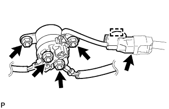
Remove the terminal cap.
-
Remove the 2 nuts and disconnect the 2 lead wires.
-
Detach the wire harness clamp and disconnect the connector.
-
Remove the 2 nuts and starter relay assembly.
-
-
REMOVE INJECTOR DRIVER ASSEMBLY
-
Disconnect the 3 injector driver assembly connectors.
-
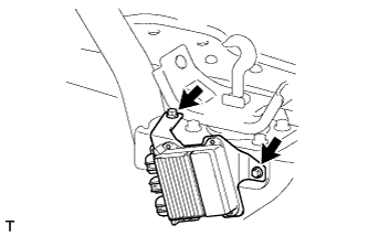
Remove the 2 bolts and injector driver assembly.
-
-
DISCONNECT RELAY BLOCK
-
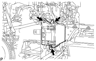
Remove the 2 bolts and nut, and disconnect the relay block.
-
-
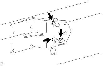
REMOVE RELAY BLOCK BRACKET ASSEMBLY
-
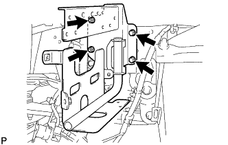
Remove the 2 bolts, 2 nuts and relay block bracket assembly.
-
-
REMOVE REAR ENGINE SIDE SHUTTER
-
Remove the 4 bolts and rear engine side shutter from the rear cab mounting bracket sub-assembly.
-
-
REMOVE REAR CAB MOUNTING BRACKET SUB-ASSEMBLY
-
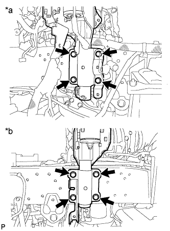
Text in Illustration *a LH *b RH Remove the 8 bolts and rear cab mounting bracket sub-assembly.
-
-
SET NO. 1 CYLINDER TO TDC/COMPRESSION
-
Text in Illustration *1 Timing Mark Set the No. 1 cylinder to TDC/compression.
Tech Tips
-
Make sure that there is free play in the No. 1 cylinder valve rocker arms and that there is no free play in the No. 4 cylinder valve rocker arms.
-
If not, turn the crankshaft 1 revolution (360°) to set the No. 1 cylinder to TDC/compression.
-
-
-
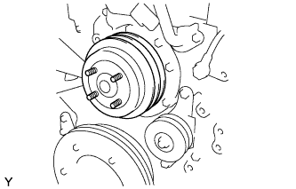
REMOVE FAN
-
Loosen the 4 nuts.
-
Remove the fan and generator V belt Click here.
-
Remove the 4 nuts and fan.
-
-
REMOVE FAN PULLEY
-
Remove the fan pulley from the engine water pump assembly.
-
-
REMOVE NO. 1 V (COOLER COMPRESSOR TO CRANKSHAFT PULLEY) BELT
-
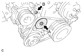
Loosen bolt A.
-
Loosen bolt B, and then remove the No. 1 V (cooler compressor to crankshaft pulley) belt.
-
-
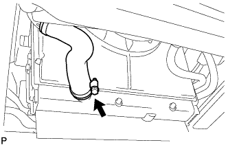
DISCONNECT NO. 1 RADIATOR HOSE
-
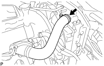
Loosen the hose clamp and disconnect the inlet radiator hose from the radiator assembly.
-
-
DISCONNECT NO. 2 RADIATOR HOSE
-
Loosen the hose clamp and disconnect the outlet radiator hose from the radiator assembly.
-
-
REMOVE RADIATOR ASSEMBLY
-
DISCONNECT COOLER COMPRESSOR ASSEMBLY
-
Remove the bolt and disconnect the cooler pipe.
-
Disconnect the connector.
-
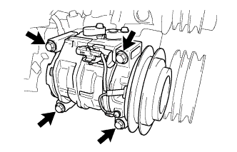
Remove the 4 bolts and disconnect the cooler compressor assembly.
Tech Tips
With the hoses connected to the cooler compressor assembly, hang the cooler compressor assembly on the vehicle body with a rope.
-
-
REMOVE GENERATOR ASSEMBLY
-
REMOVE STARTER ASSEMBLY
-
REMOVE FRONT EXHAUST PIPE ASSEMBLY
-
REMOVE EXHAUST RETARDER ASSEMBLY
-
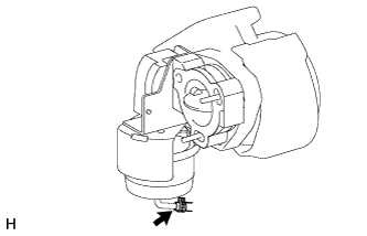
Disconnect the vacuum hose.
-
Disconnect the exhaust retarder assembly from the turbocharger sub-assembly.
-
-
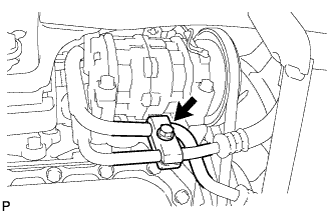
DISCONNECT PRESSURE FEED HOSE
-
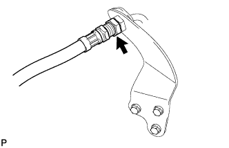
Disconnect the pressure feed hose from the oil pump to gear box tube.
-
-
DISCONNECT NO. 2 OIL RESERVOIR TO PUMP HOSE
-
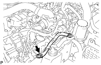
Slide the clamp and disconnect the No. 2 oil reservoir to pump hose from the power steering suction port union.
-
-
REMOVE NO. 1 HOSE SUPPORT BRACKET
-
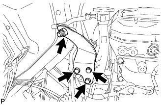
Remove the nut from the oil pump to gear box tube.
-
Remove the 3 bolts and No. 1 hose support bracket.
-
-
DISCONNECT FUEL HOSE
-
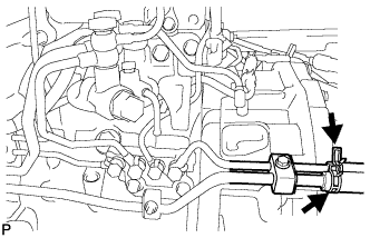
Slide the clamp and disconnect the No. 1 fuel hose from the No. 1 fuel pipe.
-
Slide the clamp and disconnect the No. 2 fuel hose from the No. 2 fuel return pipe.
-
-
DISCONNECT WIRE HARNESS
-
REMOVE EGR COOLER SUB-ASSEMBLY
-
INSTALL ENGINE HANGER
-
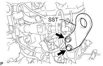
Install SST with bolts to the position shown in the illustration.
- SST
- S1220-31210
- Torque:
- 125 N*m { 1275 kgf*cm, 92 ft.*lbf }
Tech Tips
Use the following specified bolts with spring washers;
Item Specified Condition Thread Diameter 12 mm (0.472 in.) Pitch 1.75 mm (0.0689 in.) Strength Grade 9T Length 35 mm (1.38 in.)
-
-
SUPPORT ENGINE ASSEMBLY
-

Attach an engine sling device and hang the engine assembly with a chain block.
Note
Pay attention to the angle of the sling device as the engine assembly or engine hangers may be damaged or deformed if the angle is incorrect.
-
-
REMOVE PROPELLER INTERMEDIATE SHAFT ASSEMBLY
-
REMOVE MANUAL TRANSMISSION ASSEMBLY
-
REMOVE CLUTCH COVER ASSEMBLY
-
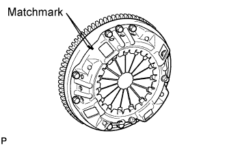
Put matchmarks on the clutch cover assembly and the flywheel sub-assembly.
-
Loosen each set bolt one turn at a time until spring tension is released.
-
Remove the set bolts, and pull off the clutch cover assembly.
Note
Do not drop the clutch disc assembly.
-
-
REMOVE CLUTCH DISC ASSEMBLY
Note
Keep the lining part of the clutch disc assembly, the pressure plate and the surface of the flywheel sub-assembly away from oil and foreign matter.
-
REMOVE ENGINE ASSEMBLY
-
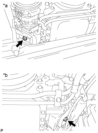
Text in Illustration *a LH *b RH Remove the 2 nuts and engine assembly from the 2 engine mounting brackets.
Note
Make sure the engine assembly is clear of all wiring and hoses.
-
-
REMOVE FLYWHEEL SUB-ASSEMBLY
-
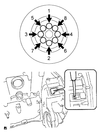
Uniformly loosen and remove the 8 flywheel set bolts in the order shown in the illustration.
Tech Tips
Insert a screwdriver through the inspection hole of the flywheel housing into the ring gear of the flywheel sub-assembly to prevent the ring gear from turning together with the crankshaft.
-
Remove the flywheel sub-assembly.
Note
The flywheel sub-assembly is heavy. When removing, be careful not to drop it on your feet.
-
-
INSTALL ENGINE STAND
-
Install the engine assembly to an engine stand with bolts.
CAUTION:
With the exception of installing the engine assembly to an engine stand or removing the engine assembly from an engine stand, do not perform any work on the engine assembly while it is suspended, as doing so is dangerous.
Note
Pay attention to the angle of the sling device as the engine assembly or engine hangers may be damaged or deformed if the angle is incorrect.
-
Remove the 2 bolts and engine hanger.
-