REAR CRANKSHAFT OIL SEAL INSTALLATION

-
INSTALL REAR ENGINE OIL SEAL
-
Apply MP grease to the rear engine oil seal lip.
-
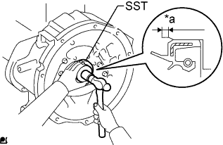
Text in Illustration *a 4 mm (0.157 in.) Using SST and a hammer, tap in a new rear engine oil seal until it is 4 mm (0.157 in.) below the upper edge of the flywheel housing.
- SST
- 09223-78010
Note
-
Be careful not to tap the rear engine oil seal at an angle.
-
Keep the gap between the rear oil seal retainer edge and the rear engine oil seal free of foreign matter.
-
-
INSTALL FLYWHEEL SUB-ASSEMBLY
-
Insert the flywheel sub-assembly slowly until it contacts the collar knock in order to prevent impact to the guide bar. Adjust the position of the flywheel and insert it completely.
-
Apply a light coat of engine oil to the threads of the flywheel set bolts and flywheel set bolt seats.
-
Temporarily install the flywheel sub-assembly with the flywheel set bolts.
-
Step 1:
-
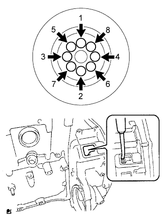
Install the flywheel set bolts in the order shown in the illustration.
- Torque:
- 86 N*m { 877 kgf*cm, 63 ft.*lbf }
Tech Tips
Insert a screwdriver through the inspection hole of the flywheel housing into the ring gear of the flywheel sub-assembly to prevent the ring gear from turning together with the crankshaft.
-
-
Step 2:
-
Mark the top of each flywheel sub-assembly bolt head with paint.
-
Tighten the bolts 45° in the order shown in the illustration.
-
Check that the paint marks are now at a 45° angle to the top.
-
-
-
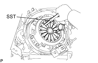
INSTALL CLUTCH DISC ASSEMBLY
-
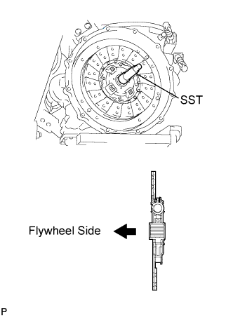
Insert SST into the clutch disc assembly, then insert them into the flywheel sub-assembly.
- SST
- 09301-00120
Note
Take care not to insert the clutch disc assembly in the wrong direction.
-
-
INSTALL CLUTCH COVER ASSEMBLY
-
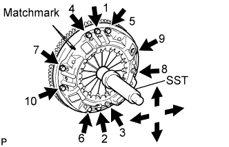
Align the matchmark on the clutch cover assembly with the one on the flywheel sub-assembly.
-
In the order shown in the illustration, tighten the 10 bolts starting from the bolt located near the knock pin on the top.
- Torque:
- 43 N*m { 440 kgf*cm, 32 ft.*lbf }
Tech Tips
-
Evenly tighten the bolts by following the order shown in the illustration.
-
Tighten the bolts after checking that the disc is in the center by lightly moving SST up and down, left and right.
- SST
- 09301-00120
-
-
INSPECT AND ADJUST CLUTCH COVER ASSEMBLY
-
Using a dial indicator with a roller instrument, check the diaphragm spring tip alignment.
Maximum misalignment 0.5 mm (0.020 in.) -
If alignment is not as specified, adjust the diaphragm spring tip alignment using SST.
- SST
- 09333-00013
-
-
INSTALL MANUAL TRANSMISSION ASSEMBLY