CYLINDER HEAD GASKET REMOVAL

-
TILT UP CAB
CAUTION:
-
Make sure that the vehicle is on a level surface before tilting the cab up.
-
Make sure that all the doors are closed before tilting the cab up.
-
Make sure that nobody is inside or near the cab when tilting it up.
-
Be sure to have 2 people tilt the cab up when a heavy object such as a roof rack or cargo carrier is installed to the cab.
-
Be sure to remove anything set on top of the cab before tilting it up.
-
Make sure that the cab is securely locked in place after it is tilted up.
-
Make sure that there are no tools, cloths, etc. left in the engine room before tilting the cab back down.
-
Make sure that the cab is securely locked in place after tilting it back down.
-
-
PRECAUTION
Note
After turning the ignition switch off, waiting time may be required before disconnecting the cable from the battery terminal. Therefore, make sure to read the disconnecting the cable from the battery terminal notice before proceeding with work Click here.
-
DISCONNECT CABLE FROM NEGATIVE BATTERY TERMINAL
Note
When disconnecting the cable, some systems need to be initialized after the cable is reconnected Click here.
-
DRAIN ENGINE OIL
-
Remove the oil filler cap.
-
Remove the oil pan drain plug and gasket, and then drain the engine oil into a container.
-
Wipe the oil pan and oil pan drain plug.
-
Install a new gasket and the oil pan drain plug.
- Torque:
- 41 N*m { 418 kgf*cm, 30 ft.*lbf }
-
-
DRAIN ENGINE COOLANT
CAUTION:
Do not remove the radiator cap sub-assembly, radiator drain cock plug or engine drain plug while the engine and radiator are still hot. Pressurized, hot engine coolant and steam may be released and cause serious burns.
-
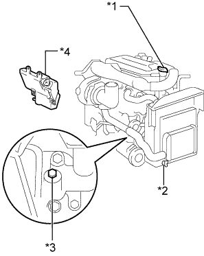
Text in Illustration *1 Radiator Cap Sub-assembly *2 Radiator Drain Cock Plug *3 Engine Drain Plug *4 Radiator Reservoir Assembly Loosen the radiator drain cock plug and engine drain plug.
-
Remove the radiator cap sub-assembly, and then drain the coolant.
Tech Tips
Collect the coolant in a container and dispose of it according to the local regulations.
-
Tighten the radiator drain cock plug by hand.
-
Tighten the engine drain plug.
- Torque:
- 27 N*m { 275 kgf*cm, 20 ft.*lbf }
-
-
REMOVE RADIATOR ASSEMBLY
-
REMOVE GENERATOR ASSEMBLY
-
REMOVE TURBOCHARGER SUB-ASSEMBLY
-
REMOVE COMMON RAIL ASSEMBLY
-
REMOVE GLOW PLUG ASSEMBLY (for Cold Area Specification Vehicles)
-
REMOVE INTAKE MANIFOLD
-
REMOVE INJECTOR ASSEMBLY
-
REMOVE FENDER SIDE APRON SUB-ASSEMBLY LH
-
Remove the 6 bolts and fender side apron sub-assembly LH.
-
-
REMOVE FENDER SIDE APRON SUB-ASSEMBLY RH
-
Remove the 6 bolts and fender side apron sub-assembly RH.
-
-
REMOVE AIR HOSE ASSEMBLY
-
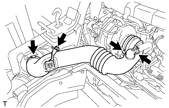
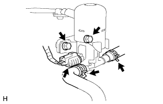
Slide the clamp and disconnect the ventilation hose from the air hose assembly.
-
Loosen the 2 hose clamps.
-
Remove the bolt and air hose assembly.
-
-
REMOVE AIR CLEANER ASSEMBLY
-
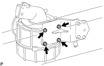
Remove the 4 nuts and air cleaner assembly from the No. 1 air cleaner stay.
-
-
REMOVE AIR CLEANER STAY
-
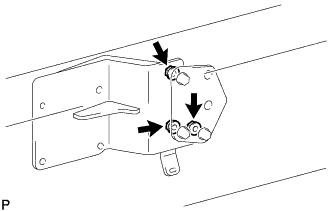
Remove the 3 nuts, No. 1 air cleaner stay and No. 2 air cleaner stay.
-
-
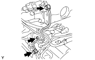
REMOVE EXHAUST BRAKE WITH BRACKET SOLENOID ASSEMBLY
-
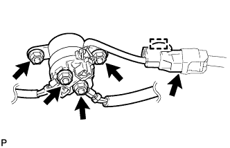
Disconnect the connector from the exhaust brake solenoid with bracket assembly.
-
Slide the 2 clips and disconnect the exhaust retarder hose and solenoid hose from the exhaust brake solenoid with bracket assembly.
-
Remove the 2 bolts and exhaust brake solenoid with bracket assembly.
-
-
REMOVE STARTER RELAY ASSEMBLY
-
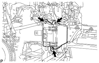
Remove the terminal cap.
-
Remove the 2 nuts and disconnect the 2 lead wires.
-
Detach the wire harness clamp and disconnect the connector.
-
Remove the 2 nuts and starter relay assembly.
-
-
REMOVE INJECTOR DRIVER ASSEMBLY
-
Disconnect the 3 injector driver assembly connectors.
-
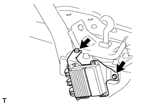
Remove the 2 bolts and injector driver assembly.
-
-
DISCONNECT RELAY BLOCK
-
Remove the 2 bolts and nut, and disconnect the relay block.
-
-
REMOVE RELAY BLOCK BRACKET ASSEMBLY
-
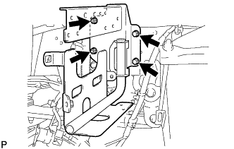
Remove the 2 bolts, 2 nuts and relay block bracket assembly.
-
-
REMOVE REAR ENGINE SIDE SHUTTER
-
Remove the 4 bolts and rear engine side shutter from the rear cab mounting bracket sub-assembly.
-
-
REMOVE REAR CAB MOUNTING BRACKET SUB-ASSEMBLY
-
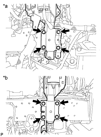
Text in Illustration *a LH *b RH Remove the 8 bolts and rear cab mounting bracket sub-assembly.
-
-
REMOVE NO. 3 NOZZLE LEAKAGE PIPE SUB-ASSEMBLY
-
Remove the nut and nozzle leakage clamp.
-
Remove the 2 union bolts, 2 gaskets and No. 3 nozzle leakage pipe sub-assembly.
-
-
DISCONNECT OIL PUMP TO GEAR BOX TUBE
-
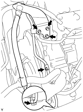
Remove the union bolt and gasket.
-
Remove the 4 bolts and disconnect the oil pump to gear box tube.
-
-
REMOVE RADIATOR PIPE SUB-ASSEMBLY
-
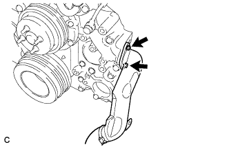
Remove the 2 bolts and radiator pipe sub-assembly.
-
Remove the O-ring.
-
-
REMOVE WATER BY-PASS PIPE SUB-ASSEMBLY
-
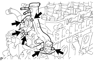
Remove the 6 bolts and water by-pass pipe sub-assembly.
-
Remove the 6 O-rings.
-
-
SET NO. 1 CYLINDER TO TDC/COMPRESSION
-
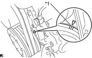
Text in Illustration *1 Timing Mark Set the No. 1 cylinder to TDC/compression.
Tech Tips
-
Make sure that there is free play in the No. 1 cylinder valve rocker arms and that there is no free play in the No. 4 cylinder valve rocker arms.
-
If not, turn the crankshaft 1 revolution (360°) to set the No. 1 cylinder to TDC/compression.
-
-
-
REMOVE NO. 1 VALVE ROCKER SHAFT SUB-ASSEMBLY
-
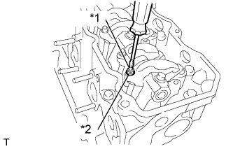
Text in Illustration *1 Valve Adjusting Screw *2 Lock Nut Loosen the lock nuts at the top of the valve rocker arms and completely loosen the valve adjusting screws.
Note
If the valve adjusting screws are not loosened, the No. 1 valve rocker shaft sub-assembly may bend when the valve rocker arm support bolts are loosened.
-
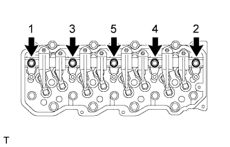
Loosen the valve rocker arm support bolts in the order shown in the illustration.
-
Remove the 5 bolts and No. 1 valve rocker shaft sub-assembly.
-
-
REMOVE VALVE PUSH ROD
Tech Tips
Organize the parts so that each part location can be remembered for reassembly.
-
REMOVE VALVE LIFTER
Tech Tips
Organize the parts so that each part location can be remembered for reassembly.
-
REMOVE VALVE BRIDGE
Tech Tips
Organize the parts so that each part location can be remembered for reassembly.
-
REMOVE CYLINDER HEAD SUB-ASSEMBLY
-
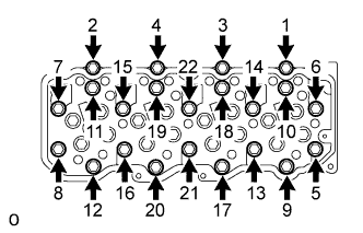
Loosen the cylinder head bolts in the order shown in the illustration and remove the bolts.
-
Lift and remove the cylinder head sub-assembly from the cylinder block.
-
-
REMOVE CYLINDER HEAD GASKET
-
Remove the cylinder head gasket.
-
-
INSPECT CYLINDER HEAD SET BOLT
-
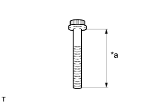
Text in Illustration *a Measurement Length Using a vernier caliper, measure the length of the cylinder head set bolt from the seat to the end.
Standard length 126 mm (4.96 in.) Maximum length 129 mm (5.07 in.) If the length is more than the maximum, replace the cylinder head set bolt.
-
-
INSPECT CYLINDER HEAD SUB-ASSEMBLY
-
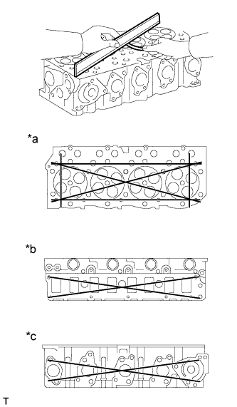
Text in Illustration *a Cylinder Block Side *b Intake Manifold Side *c Exhaust Manifold Side Using a straightedge and feeler gauge, measure the warpage on the cylinder block side and the intake manifold side and exhaust manifold side.
Maximum warpage 0.10 mm (0.00394 in.) If the warpage is more than the maximum, replace the cylinder head sub-assembly.
-
Using a dye penetrant, check the cylinder head sub-assembly for cracks.
If there are cracks, replace the cylinder head sub-assembly.
-