ENGINE ON-VEHICLE INSPECTION

-
TILT UP CAB
CAUTION:
-
Make sure that the vehicle is on a level surface before tilting the cab up.
-
Make sure that all the doors are closed before tilting the cab up.
-
Make sure that nobody is inside or near the cab when tilting it up.
-
Be sure to have 2 people tilt the cab up when a heavy object such as a roof rack or cargo carrier is installed to the cab.
-
Be sure to remove anything set on top of the cab before tilting it up.
-
Make sure that the cab is securely locked in place after it is tilted up.
-
Make sure that there are no tools, cloths, etc. left in the engine room before tilting the cab back down.
-
Make sure that the cab is securely locked in place after tilting it back down.
-
-
INSPECT ENGINE COOLANT
-
INSPECT ENGINE OIL
-
INSPECT BATTERY
-
INSPECT DRIVE BELT
-
INSPECT AIR CLEANER FILTER ELEMENT SUB-ASSEMBLY
-
Remove the air cleaner filter element sub-assembly.
-
Visually check that the air cleaner filter element sub-assembly is not excessively damaged or oily. If necessary, replace the air cleaner filter element sub-assembly.
Tech Tips
-
If there is any dirt or a blockage in the air cleaner filter element sub-assembly, clean it with compressed air.
-
If any dirt or a blockage remains even after cleaning the air cleaner filter element sub-assembly with compressed air, replace it.
-
-
Install the air cleaner filter element sub-assembly.
-
-
CHECK IDLE SPEED AND MAXIMUM SPEED
Note
Turn all electrical systems and the A/C off.
-
Warm up and stop the engine.
-
Replace the normal DLC3 cable (12 V specification) for the intelligent tester with the 24 V DLC3 cable.
Note
Be sure to use the 24 V DLC3 cable when connecting the intelligent tester to the DLC3. Using the normal DLC3 cable (12 V specification) will cause damage to the tester.
-
Connect the intelligent tester to the DLC3.
-
Turn the ignition switch to ON.
-
Enter the following menus: Powertrain / Engine and ECT / Data List
Tech Tips
Refer to the intelligent tester operator's manual for further information regarding the selection of the Data List.
-
Inspect the engine idle speed.
Standard idle speed 600 to 700 rpm -
Fully depress the accelerator pedal.
-
Check the maximum speed.
Maximum speed 3300 to 3400 rpm -
Turn the ignition switch off.
-
Disconnect the intelligent tester from the DLC3.
-
-
INSPECT COMPRESSION
-
Warm up and stop the engine.
-
Remove the oil filler cap sub-assembly.
-
Remove the 2 bolts and cylinder head cover sub-assembly.
-
for Cold Area Specification Vehicles:
Remove the 4 glow plug assemblies Click here.
-
Remove the 4 bolts from the 4 glow plug holes.
-
Remove the bolt and disconnect the wire harness clamp bracket.
-
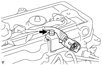
Disconnect the 4 connectors from the 4 injector assemblies.
-
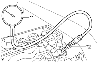
Text in Illustration *1 SST (Compression Gauge) *2 SST (Attachment) Insert SST (attachment) into the glow plug hole.
- SST
- 09992-00026
-
Connect SST (compression gauge) to SST (attachment).
-
While cranking the engine, measure the compression pressure.
Standard compression pressure 3200 kPa (32.6 kgf/cm2, 464 psi) or higher Minimum compression pressure 2700 kPa (27.5 kgf/cm2, 392 psi) Maximum difference between each cylinder 290 kPa (3.0 kgf/cm2, 42 psi) or less Note
-
Use a fully-charged battery so that the engine speed can be increased to 280 rpm or more.
-
Inspect the other cylinders in the same way.
-
Measure the compression pressure in as short a time as possible.
If the cylinder compression is low, pour a small amount of engine oil into the cylinder through the glow plug hole and inspect the compression again.
Tech Tips
-
If adding oil increases the compression, the piston rings and/or cylinder bore may be worn or damaged.
-
If the pressure stays low, a valve may be stuck or seated improperly, or there may be leakage from the head gasket.
-
-
Remove SST (compression gauge) and SST (attachment).
-
Connect the 4 connectors to the 4 injector assemblies.
-
Connect the wire harness clamp bracket with the bolt.
- Torque:
- 29 N*m { 291 kgf*cm, 21 ft.*lbf }
-
Install the 4 bolts to the 4 glow plug holes.
- Torque:
- 23 N*m { 229 kgf*cm, 17 ft.*lbf }
-
for Cold Area Specification Vehicles:
Install the 4 glow plug assemblies Click here.
-
Install the cylinder head cover sub-assembly with the 2 bolts.
- Torque:
- 29 N*m { 291 kgf*cm, 21 ft.*lbf }
-
Install the oil filler cap sub-assembly.
-
-
INSPECT DIESEL SMOKE
Standard value (Black smoke) 10% or less