CYLINDER BLOCK INSPECTION

-
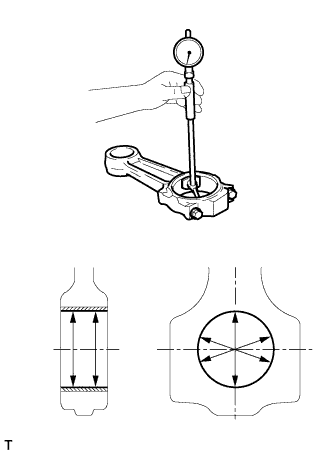
INSPECT CONNECTING ROD THRUST CLEARANCE
-
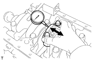
Using a dial indicator, measure the thrust clearance while moving the connecting rod back and forth.
Standard thrust clearance 0.200 to 0.520 mm (0.00787 to 0.0205 in.) Maximum thrust clearance 0.60 mm (0.0236 in.) If the thrust clearance is greater than the maximum, replace the connecting rod. If necessary, replace the crankshaft.
-
-
INSPECT CRANKSHAFT THRUST CLEARANCE
-
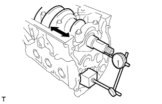
Using a dial indicator, measure the thrust clearance while prying the crankshaft back and forth.
Standard thrust clearance 0.050 to 0.220 mm (0.00197 to 0.00866 in.) Maximum thrust clearance 0.40 mm (0.0157 in.) If the thrust clearance is greater than the maximum, replace the crankshaft or thrust washers as a set.
-
-
INSPECT CONNECTING ROD BOLT
-

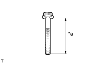
Text in Illustration *a Measurement Length Using a vernier caliper, measure the length of the connecting rod bolt from the seat to end.
Standard bolt length 59.00 mm (2.3228 in.) Maximum bolt length 61.5 mm (2.421 in.) If the length is greater than the maximum, replace the connecting rod bolt.
-
-
INSPECT CYLINDER LINER
-
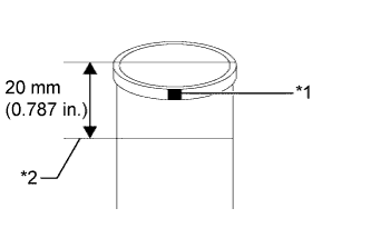
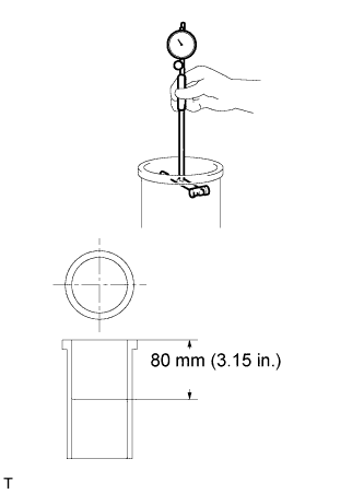
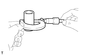
Text in Illustration *1 Symbol *2 Measurement Length Using a micrometer, measure the outside diameter of the cylinder liner.
Standard Outside Diameter Symbol Diameter A 106.982 to 106.989 mm (4.2119 to 4.2122 in.) B 106.990 to 106.995 mm (4.2122 to 4.2124 in.) C 106.996 to 107.004 mm (4.2124 to 4.2128 in.) If the diameter is less than the standard, replace the cylinder liner.
-
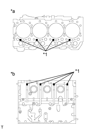
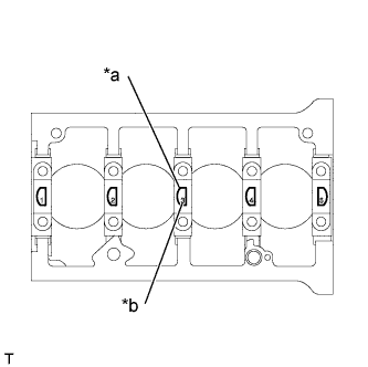
Text in Illustration *1 Symbol *a Cylinder Block Side *b Intake Manifold Side Using a cylinder gauge, measure the inside diameter of the cylinder block.
Standard Inside Diameter Symbol Diameter A 107.000 to 107.008 mm (4.2126 to 4.2129 in.) B 107.008 to 107.014 mm (4.2129 to 4.2131 in.) C 107.014 to 107.022 mm (4.2131 to 4.2135 in.) If the diameter is greater than the standard, replace the cylinder block.
-
-
INSPECT CYLINDER BLOCK FOR WARPAGE
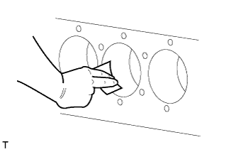
Tech Tips
Before the measurement, remove carbon deposits from the upper end inside the cylinder liner with a scraper or emery paper (recommended: No. 150), working in a circular direction. Make sure that there are no scratches inside the cylinder liner.
-
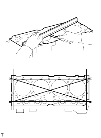
Using a precision straight edge and feeler gauge, measure the warpage of the surface in contact with the cylinder head.
Maximum warpage 0.10 mm (0.00394 in.) If the warpage is greater than the maximum, replace the cylinder block.
-
Visually check the cylinders for vertical scratches.
If deep scratches are found, rebore all 4 cylinders. If necessary, replace the cylinder block.
-
-
INSPECT CYLINDER BORE
-
Using a cylinder gauge, measure the cylinder liner inside diameter at the 4 points in the piston boss and thrust direction, as shown in the illustration.
Standard inside diameter 104.012 to 104.036 mm (4.0950 to 4.0959 in.) Maximum inside diameter 104.15 mm (4.1004 in.) If the diameter is greater than the maximum, replace the cylinder liner with a new one.
-
-
INSPECT PISTON
-
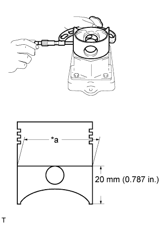
Text in Illustration *a Diameter Using a micrometer, measure the piston diameter at the location shown in the illustration.
Standard piston diameter 103.936 to 103.952 mm (4.0920 to 4.0926 in.) If the diameter is less than the standard, replace the piston with a new one.
-
-
INSPECT PISTON OIL CLEARANCE
-
Subtract the piston diameter measurement from the cylinder liner inside diameter measurement.
Standard oil clearance 0.06 to 0.1 mm (0.00236 to 0.00394 in.) If the clearance is greater than the standard, replace the cylinder liner and/or piston with a new one.
Tech Tips
Apply the value measured at the most worn point to the cylinder liner inside diameter.
-
-
INSPECT PISTON PIN OIL CLEARANCE
-
Using a micrometer, measure the piston pin diameter.
Standard piston pin diameter 36.989 to 37.000 mm (1.4563 to 1.4567 in.) Minimum piston pin diameter 36.96 mm (1.4551 in.) If the diameter is less than the minimum, replace the piston pin with a new one.
Tech Tips
Never grind the piston pin because its surface is coated with a special material.
-
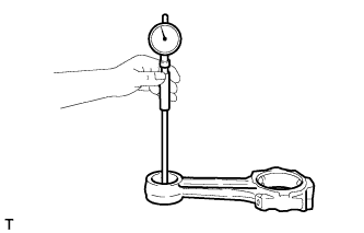
Using a cylinder gauge, measure the connecting rod bush inside diameter.
Standard bush inside diameter 37.035 to 37.045 mm (1.4581 to 1.4585 in.) Maximum bush inside diameter 37.10 mm (1.4606 in.) If the inside diameter is greater than the maximum, replace the connecting rod bush with a new one.
-
Subtract the diameter measurement of the piston pin from the inside diameter measurement of the connecting rod bush.
Standard oil clearance 0.035 to 0.056 mm (0.00138 to 0.00220 in.) Maximum oil clearance 0.08 mm (0.00315 in.) If the oil clearance is greater than the maximum, replace the piston pin and connecting rod bush as a set.
-
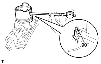
Using a cylinder gauge, measure the piston pin boss inside diameter while turning the gauge 90°.
Standard piston pin hole inside diameter 36.987 to 37.003 mm (1.4562 to 1.4568 in.) Maximum piston pin hole inside diameter 37.05 mm (1.4587 in.) If the piston pin hole inside diameter is greater than the maximum, replace the piston with a new one.
-
Subtract the diameter measurement of the piston pin from the inside diameter measurement of the piston pin hole.
Standard oil clearance -0.013 to 0.014 mm (-0.000512 to 0.000551 in.) Maximum oil clearance 0.05 mm (0.00197 in.) Tech Tips
If the clearance is greater than the maximum, replace the piston or piston pin.
-
-
INSPECT RING GROOVE CLEARANCE
-
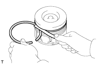
Insert the piston ring into the piston ring groove.
-
Using a feeler gauge, measure the clearance between the piston ring and piston ring groove.
Standard Groove Clearance Item Clearance 1st 0.11 to 0.15 mm (0.00433 to 0.00591 in.) 2nd 0.07 to 0.11 mm (0.00276 to 0.00433 in.) Oil 0.02 to 0.06 mm (0.000787 to 0.00236 in.) Maximum groove clearance 0.30 mm (0.0118 in.) If the clearance is greater than the maximum, measure the width of the piston ring and piston ring groove individually and replace any parts that do not meet the limit with new ones.
-
Using a feeler gauge, measure the dimension of each groove.
Standard Groove Width Item Width 1st 2.58 to 2.60 mm (0.1016 to 0.1024 in.) 2nd 2.06 to 2.08 mm (0.0811 to 0.0819 in.) Oil 4.01 to 4.03 mm (0.1579 to 0.1587 in.) Maximum Groove Width Item Width 1st 3.10 mm (0.1220 in.) 2nd 2.20 mm (0.0866 in.) Oil 4.08 mm (0.1606 in.) If the dimension is greater than the maximum, replace the piston and piston rings as a set.
-
Using a micrometer, measure the piston ring thickness.
Standard Ring Thickness Item Thickness 1st 2.47 to 2.49 mm (0.0972 to 0.0980 in.) 2nd 1.97 to 1.99 mm (0.0776 to 0.0783 in.) Oil 4.97 to 4.99 mm (0.1957 to 0.1965 in.) Minimum Ring Thickness Item Thickness 1st 2.32 mm (0.0913 in.) 2nd 1.82 mm (0.0717 in.) Oil 4.95 mm (0.1949 in.) If the thickness is less than the minimum, replace the piston ring.
-
-
INSPECT CONNECTING ROD SUB-ASSEMBLY
-
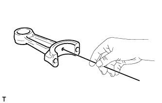
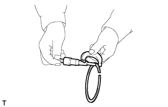
Check that there is no clogging in the lubrication passage to the connecting rod small end.
If there is any clogging, blow air through the lubrication passage using an air gun, or clean by inserting a wire.
-
-
INSPECT CRANKSHAFT ASSEMBLY
Tech Tips
Before the inspection, clean the crankshaft with a commercial cleaning agent and clean the lubrication passages using an air gun.
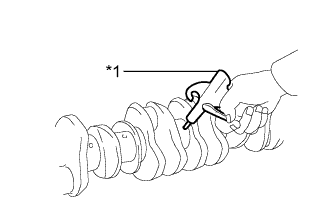
Text in Illustration *1 Air Gun
-
Performing the dye penetrant test, check the crankshaft for cracks.
Tech Tips
Pay special attention to the finished section and oil holes of the crankshaft journal and crankshaft pin.
-
Visually check the condition of the crankshaft journal and pin for damage or wear.
If any damage is found, replace the crankshaft with a new one.
-
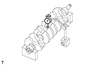
Inspect for runout.
-
Place the crankshaft on V-blocks.
-
Using a dial gauge, measure the circle runout of the crankshaft at the center journal.
Maximum runout 0.04 mm (0.00157 in.) If the circle runout is greater than the maximum, replace the crankshaft with a new one.
-
-
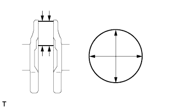
Using a micrometer, measure the main journal outside diameter.
Standard journal diameter 72.94 to 72.96 mm (2.8717 to 2.8724 in.) Minimum journal diameter 71.76 mm (2.8252 in.) If the diameter is less than the minimum, replace the crankshaft with a new one.
-
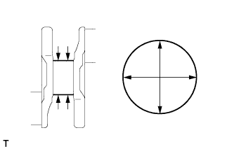
Check each main journal for taper and distortion as shown in the illustration.
Maximum taper and distortion 0.01 mm (0.000394 in.) If the taper and distortion is greater than the maximum, replace the crankshaft.
-
Using a micrometer, measure the crankshaft pin outside diameter.
Standard crankshaft pin diameter 61.94 to 61.96 mm (2.4386 to 2.4394 in.) Minimum crankshaft pin diameter 60.76 mm (2.3921 in.) If the diameter is less than the minimum, replace the crankshaft with a new one.
-
Check each crankshaft pin for taper and distortion as shown in the illustration.
Maximum taper and distortion 0.01 mm (0.000394 in.) If the taper and distortion is greater than the maximum, replace the crankshaft.
-
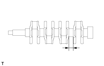
Using a vernier caliper, measure the dimension of the crankshaft No. 4 journal.
Standard journal dimension 34.00 to 34.08 mm (1.3386 to 1.3417 in.) Maximum journal dimension 34.48 mm (1.3574 in.) If the dimension is greater than the maximum, replace the crankshaft.
-
Visually check if there are any cracks on the crankshaft.
-
Check if the oil holes of the crankshaft are blocked. If any blockage is found, replace the crankshaft.
-
-
INSPECT CRANKSHAFT BEARING CAP SET BOLT
-
Text in Illustration *a Measurement Length Using a vernier caliper, measure the length of the crankshaft bearing cap set bolt from the seat to end.
Standard bolt length 92.80 to 93.80 mm (3.6535 to 3.6929 in.) Maximum bolt length 95.00 mm (3.7401 in.) If the length is greater than the maximum, replace the crankshaft bearing cap set bolt.
-
-
INSPECT CRANKSHAFT BEARING CAP
-
Text in Illustration *a Front Mark *b Journal No. Install the bearing caps to the cylinder block.
-
Apply a light coat of engine oil to the threads of the bearing cap bolts.
-
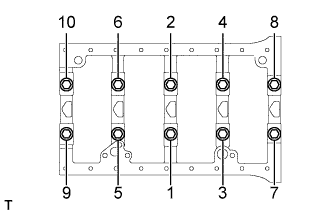
Uniformly tighten the 10 bolts in the order shown in the illustration.
- Torque:
- 60 N*m { 610 kgf*cm, 44 ft.*lbf }
-
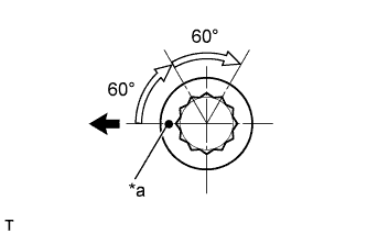
Text in Illustration *a Paint Mark 
Front Mark the front side of the bolts with paint.
-
Retighten the bolts 60° in the same order as step (c).
-
Perform step (e) again.
-
Check that each painted mark is now at a 120° angle to the front.
-
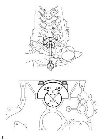
Using a cylinder gauge, measure the crankshaft bearing cap inside diameter at 3 points (X, Y, Z in the illustration).
Standard crankshaft bearing cap inside diameter 77.985 to 78.00 mm (3.0703 to 3.0709 in.) Maximum crankshaft bearing cap inside diameter 78.20 mm (3.0787 in.) If the inside diameter is greater than the maximum, carry out boring after overlay welding or replace the cylinder block with a new one.
Tech Tips
When installing the main bearing caps, make sure to return them to their original locations according to the number stamped on the caps.
-
-
INSPECT CRANKSHAFT OIL CLEARANCE
Tech Tips
The upper bearings have an oil hole, however, the lower bearings do not.
-
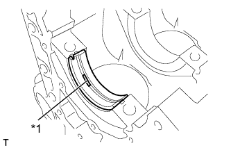
Text in Illustration *1 Oil Hole Align the key of the bearing with the keyway of the cylinder block, and push in the upper bearing.
Note
Do not apply engine oil to the bearing or its contact surface.
-
Align the key of the bearing with the keyway of the main bearing cap, and push in the lower bearing.
Note
Do not apply engine oil to the bearing or its contact surface.
-

Text in Illustration *a Front Mark *b Journal No. Install the bearing caps onto the cylinder block.
-
Apply a light coat of engine oil to the threads of the bearing cap bolts.
-
Uniformly tighten the 10 bolts in the order shown in the illustration.
- Torque:
- 60 N*m { 610 kgf*cm, 44 ft.*lbf }
-

Text in Illustration *a Paint Mark Front Mark the front side of the bolts with paint.
-
Retighten the bolts 60° in the same order as step (e).
-
Perform step (g) again.
-
Check that each painted mark is now at a 120° angle to the front.
-
Using a cylinder gauge, measure the crankshaft bearing inside diameter at 3 points (X, Y, Z in the illustration).
Standard crankshaft bearing inside diameter 73.01 to 73.04 mm (2.8744 to 2.8756 in.) Maximum crankshaft bearing inside diameter 73.30 mm (2.8858 in.) Note
Do not damage the crankshaft bearing.
If the inside diameter is greater than the maximum, replace the bearing with a new one.
Tech Tips
When installing the bearing caps, make sure to return them to their original locations according to the number stamped on the caps.
-
Subtract the crankshaft journal diameter measurement from the bearing inside diameter measurement.
Standard oil clearance 0.051 to 0.102 mm (0.00201 to 0.00402 in.) Maximum oil clearance 0.20 mm (0.00787 in.) If the oil clearance is greater than the maximum, use an undersize bearing and correct or regrind the crankshaft so that the oil clearance becomes 0.20 mm (0.00787 in.) or less.
Undersize Bearing Diameter Item Diameter STD 72.94 to 72.96 mm (2.8717 to 2.8724 in.) U/S 0.25 72.69 to 72.71 mm (2.8618 to 2.8626 in.) U/S 0.50 72.44 to 72.46 mm (2.8520 to 2.8528 in.) U/S 0.75 72.19 to 72.21 mm (2.8421 to 2.8429 in.) U/S 1.00 71.94 to 71.96 mm (2.8323 to 2.8330 in.) Tech Tips
Make sure to replace the upper and lower main bearings as one set.
-
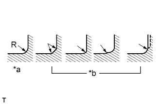
Text in Illustration *a CORRECT *b INCORRECT Machined dimension of fillet radius
Main crankshaft journal radius 3.00 to 3.50 mm (0.1181 to 0.1378 in.)
-
-
-
INSPECT CONNECTING ROD OIL CLEARANCE
-
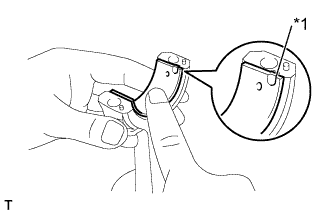
Text in Illustration *1 Claw Align the claw of the bearing with the claw grooves of the connecting rod and connecting cap.
Note
Clean the back side of the bearing and the bearing surface of the connecting rod. The surfaces should be free of dust and oil.
-
Tighten the connecting rod bolts.
-
Install the bearing cap.
Note
Be careful of the installation direction of the bearing cap.
-
Uniformly tighten the bolts several times.
-
Retighten the connecting rod bolts.
- Torque:
- 30 N*m { 300 kgf*cm, 22 ft.*lbf }
-
Mark the front side of the bolts with paint.
-
-
Text in Illustration *a Paint Mark Front Retighten the bolts 60°.
-
Perform step (c) again.
-
Using a cylinder gauge, measure the connecting rod big end inside diameter.
Standard big end inside diameter (with bearing) 61.991 to 62.022 mm (2.4406 to 2.4418 in.) Maximum big end inside diameter (with bearing) 62.06 mm (2.4433 in.) If the result is greater than the maximum, replace the connecting rod bearing.
-
Subtract the inside diameter measurement of the connecting rod from the diameter measurement of the crankshaft pin.
Standard clearance 0.031 to 0.082 mm (0.00122 to 0.00323 in.) Maximum oil clearance 0.20 mm (0.00787 in.) If the result is greater than the maximum, use an undersize bearing and correct or regrind the crankshaft so that the oil clearance becomes 0.20 mm (0.00787 in.) or less.
Undersize Bearing Diameter Item Diameter STD 61.94 to 61.96 mm (2.4386 to 2.4394 in.) U/S 0.25 61.69 to 61.71 mm (2.4287 to 2.4295 in.) U/S 0.50 61.44 to 61.46 mm (2.4189 to 2.4197 in.) U/S 0.75 61.19 to 61.21 mm (2.4090 to 2.4098 in.) U/S 1.00 60.94 to 60.96 mm (2.3992 to 2.4000 in.)
-
Text in Illustration *a CORRECT *b INCORRECT Machined dimension of fillet radius
Crankshaft pin radius 3.50 to 4.00 mm (0.1378 to 0.1575 in.)
-
-
-
INSPECT CAMSHAFT OIL CLEARANCE
-
Measure the oil clearance of the camshaft journal.
Text in Illustration Front
-
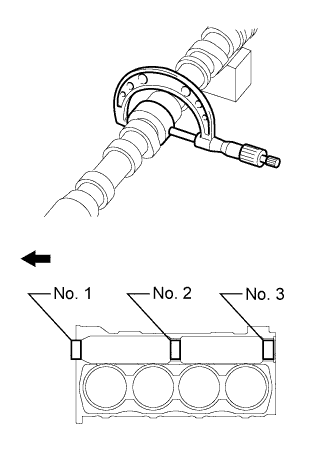
Using a micrometer, measure the camshaft journal outside diameter.
Standard Journal Outside Diameter Item Diameter No. 1 56.95 to 56.97 mm (2.2421 to 2.2429 in.) No. 2 56.75 to 56.77 mm (2.2343 to 2.2350 in.) No. 3 56.55 to 56.57 mm (2.2264 to 2.2272 in.) If the outside diameter of each camshaft journal is less than the standard, replace the camshaft.
-
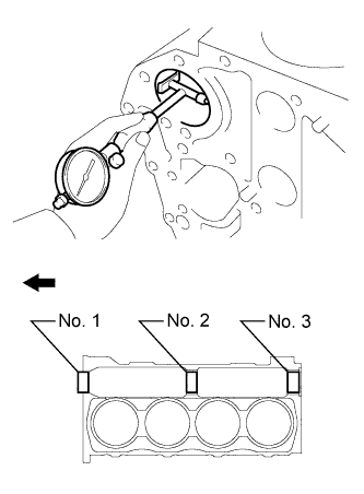
Using a cylinder gauge, measure the camshaft bearing inside diameter.
Text in Illustration Front Standard Inside Diameter Item Diameter No. 1 57.035 to 57.135 mm (2.2455 to 2.2494 in.) No. 2 56.835 to 56.935 mm (2.2376 to 2.2415 in.) No. 3 56.635 to 56.735 mm (2.2297 to 2.2337 in.) If the inside diameter of each camshaft bearing is greater than the standard, replace the camshaft bearing.
-
Subtract the outside diameter measurement of the camshaft journal from the inside diameter measurement of the camshaft bearing.
Standard oil clearance 0.030 to 0.120 mm (0.00118 to 0.00472 in.) Maximum oil clearance 0.15 mm (0.00590 in.) If the oil clearance is greater than the maximum, replace the camshaft or camshaft bearing.
-
-