CAMSHAFT REMOVAL

-
REMOVE ENGINE UNDER COVER
-
DISCONNECT CABLE FROM NEGATIVE BATTERY TERMINAL
-
DRAIN ENGINE OIL
-
Remove the oil filler cap sub-assembly.
-
Remove the drain plug and gasket from the oil pan and drain engine oil into a container.
-
Clean the drain plug.
-
Install the drain plug with a new gasket.
- Torque:
- 41 N*m { 418 kgf*cm, 30 ft.*lbf }
-
-
DRAIN ENGINE COOLANT
CAUTION:
Do not loosen the radiator drain cock plug and engine drain plug while the engine and radiator are still hot. Pressurized, hot engine coolant and steam may be released and cause serious burns.
-
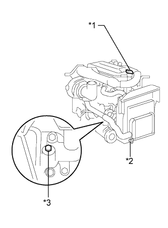
Text in Illustration *1 Radiator Cap Sub-assembly *2 Radiator Drain Cock Plug *3 Engine Drain Plug Loosen the radiator drain cock plug and engine drain plug.
-
Remove the radiator cap sub-assembly, then drain the coolant.
-
Close the radiator drain cock plug.
-
Tighten the engine drain plug.
- Torque:
- 27 N*m { 275 kgf*cm, 20 ft.*lbf, for the engine drain plug }
-
-
DRAIN POWER STEERING FLUID
-
REMOVE CYLINDER HEAD GASKET
Tech Tips
-
DISCONNECT NO. 2 OIL RESERVOIR TO PUMP HOSE
-
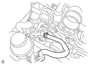
Disconnect the No. 2 oil reservoir to pump hose.
-
-
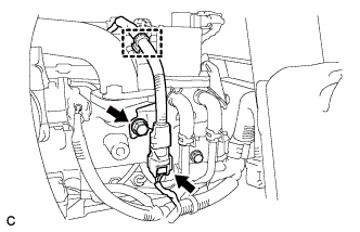
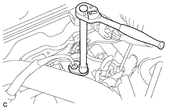
REMOVE PRESSURE FEED HOSE
-
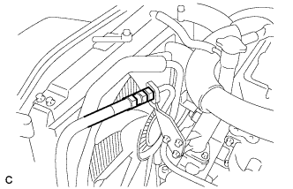
Using a union nut wrench (19 mm), separate the pressure feed hose.
-
Remove the gasket from the pressure feed hose.
-
-
REMOVE VANE PUMP ASSEMBLY
-
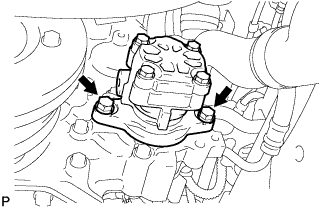
Remove the 2 bolts and vane pump assembly.
-
Remove the O-ring from the vane pump assembly.
-
-
REMOVE WATER PUMP ASSEMBLY
-

Remove the 8 bolts and water pump assembly.
-
-
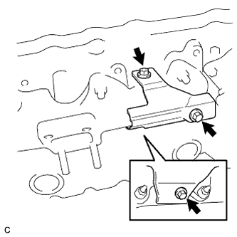
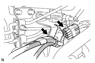
REMOVE INTAKE AIR TEMPERATURE SENSOR
-
Disconnect the intake air temperature sensor connector.
-
Remove the bolt.
-
Disconnect the wire harness clamp.
-
Remove the bracket from the intake air temperature sensor connector.
-
Using a union nut wrench, remove the intake air temperature sensor and gasket.
Note
Do not damage the intake air temperature sensor.
-
-
REMOVE INTAKE MANIFOLD
-

Remove the 8 bolts, 2 nuts and remove the intake manifold.
-
-
REMOVE EXHAUST MANIFOLD
-
Remove the 3 bolts and exhaust manifold heat insulator.
-
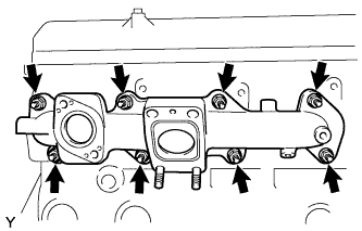
Remove the 8 nuts and exhaust manifold.
-
-
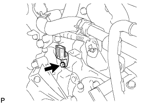
REMOVE CRANKSHAFT POSITION SENSOR
-
Remove the bolt and crankshaft position sensor.
-
Remove the O-ring from the crankshaft position sensor.
-
-
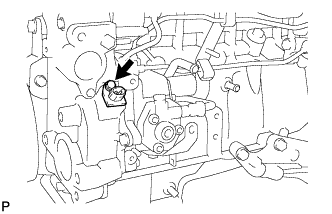
REMOVE CAMSHAFT POSITION SENSOR
-
Remove the bolt and camshaft position sensor.
-
Remove the O-ring from the camshaft position sensor.
-
-
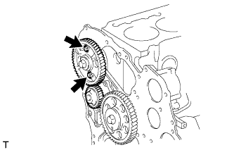
SET NO. 1 CYLINDER TO TDC/COMPRESSION
-
Text in Illustration *1 Timing Mark Set the No. 1 cylinder to TDC/compression.
Tech Tips
-
Make sure that there is free play in the No. 1 cylinder rocker arms and that there is no free play in the No. 4 cylinder rocker arms.
-
If not, turn the crankshaft 1 revolution (360°) to set the No. 1 cylinder to TDC/compression.
-
-
-
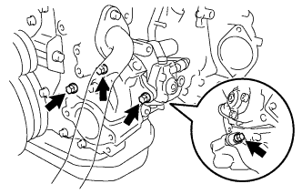
REMOVE VACUUM PIPE
-
Remove the union bolt, bolt, 2 gaskets and vacuum pipe.
-
-
REMOVE VACUUM PUMP OIL PIPE SUB-ASSEMBLY
-
Remove the 3 union bolts, gaskets and vacuum pump oil pipe sub-assembly.
-
-
REMOVE VACUUM PUMP ASSEMBLY
-

Remove the 2 nuts and vacuum pump assembly.
-
-
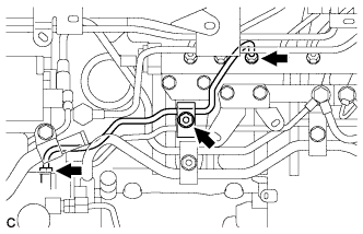
REMOVE FUEL PIPE SUB-ASSEMBLY
-
Remove the 2 bolts and nut, and then remove the 3 fuel pipe clamps.
-
Remove the union bolt and gaskets, and then remove the fuel pipe sub-assembly.
-
-
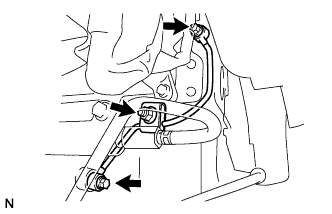
REMOVE FUEL FILTER TO INJECTION PUMP FUEL PIPE
-
Disconnect the wire harness connector.
-
Disconnect the 2 wire harness clamps.
-
Remove the nut and fuel pipe clamp.
-
Using a union nut wrench (17 mm), loosen the 2 union nuts.
-
Remove the fuel filter to injection pump fuel pipe.
-
-
REMOVE NO. 3 NOZZLE LEAKAGE PIPE SUB-ASSEMBLY
-
Remove the nut and the fuel pipe clamp.
-
Remove the 2 union bolts, 4 gaskets and No. 3 nozzle leakage pipe sub-assembly.
-
-
REMOVE COMMON RAIL ASSEMBLY
-

Disconnect the fuel pressure sensor connector.
-
Loosen the clip and separate the fuel hose.
-
Remove the 2 bolts and the common rail assembly.
-
-
REMOVE FUEL RETURN PIPE SUB-ASSEMBLY
-

Remove the 2 union bolts and 5 gaskets.
-
Remove the fuel return pipe sub-assembly.
-
-
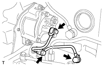
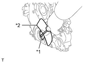
REMOVE SUPPLY PUMP ASSEMBLY
-
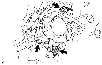
Disconnect the 2 connectors.
-
Remove the bolt, and then separate the holder clip.
-
Remove the 4 bolts and the supply pump assembly.
-
Remove the O-ring from the timer cover.
-
-
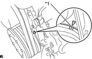
REMOVE CRANKSHAFT PULLEY
-
Tech Tips
Insert a screwdriver through the inspection hole of the flywheel housing into the ring gear of the flywheel to keep it from turning together with the crankshaft.
-
-
REMOVE FLYWHEEL HOUSING STAY LH
-
Remove the 4 bolts and flywheel housing stay LH.
-
-
REMOVE FLYWHEEL HOUSING STAY RH
-
Remove the 4 bolts and flywheel housing stay RH.
-
-
REMOVE OIL PAN SUB-ASSEMBLY
-
Remove the 26 bolts.
-

Insert the blade of an oil pan seal cutter between the crankcase and oil pan. Cut through the applied sealer and remove the oil pan.
Note
Do not damage the contact surfaces of the cylinder block or oil pan.
-
-
REMOVE TIMING GEAR CASE
-

Remove the 15 bolts.
-
Using a screwdriver with its tip wrapped in protective tape, pry out the timing gear case.
Note
Do not damage the contact surfaces of the timing gear case or cylinder block.
-
-
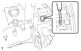
REMOVE TIMING CHAIN OR BELT COVER OIL SEAL
-
Text in Illustration *1 Protective Tape *2 Shop Rag or Piece of Cloth Using a screwdriver with its tip wrapped in protective tape, pry out the oil seal.
Tech Tips
Use a shop rag or piece of cloth to prevent damage to the timing gear case.
-
-
REMOVE CAMSHAFT
-
Remove the 2 bolts and camshaft.
-