VALVE CLEARANCE ADJUSTMENT

-
REMOVE INJECTOR ASSEMBLY
Tech Tips
-
CHECK VALVE CLEARANCE
-

Text in Illustration *1 Timing Mark Set the No. 1 cylinder to TDC/compression.
Tech Tips
-
Make sure that there is free play in the No. 1 cylinder rocker arms and that there is no free play in the No. 4 cylinder rocker arms.
-
If not, turn the crankshaft 1 revolution (360°) to set the No. 1 cylinder to TDC/compression.
-
-
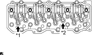
Text in Illustration *1 No. 1 Intake Valve *2 No. 3 Exhaust Valve Check the valve clearance of the No. 1 cylinder intake valve and the No. 3 cylinder exhaust valve.
Standard valve clearance (Cold) Intake 0.30 mm (0.0118 in.) Exhaust 0.45 mm (0.0177 in.) Note
Do not apply excessive force to the valve adjusting screw.
Tech Tips
If the clearance is not as specified, record the out-of-specification measurement, then adjust the valve clearance.
-
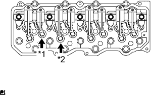
Text in Illustration *1 No. 1 Exhaust Valve *2 No. 2 Intake Valve Check the valve clearance of the No. 1 cylinder exhaust valve and the No. 2 cylinder intake valve.
Standard valve clearance (Cold) Intake 0.30 mm (0.0118 in.) Exhaust 0.45 mm (0.0177 in.) Note
Do not apply excessive force to the valve adjusting screw.
Tech Tips
If the clearance is not as specified, record the out-of-specification measurement, then adjust the valve clearance.
-
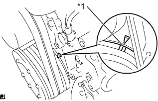
Text in Illustration *1 Timing Mark Turn the crankshaft 360° clockwise to set the No. 4 cylinder to TDC/compression.
Tech Tips
-
Make sure that there is free play in the No. 4 cylinder rocker arms and that there is no free play in the No. 1 cylinder rocker arms.
-
If not, turn the crankshaft 1 revolution (360°) to set the No. 4 cylinder to TDC/compression.
-
-
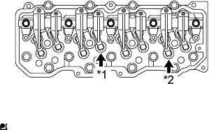
Text in Illustration *1 No. 2 Exhaust Valve *2 No. 4 Intake Valve Check the valve clearance of the No. 2 cylinder exhaust valve and the No. 4 cylinder intake valve.
Standard valve clearance (Cold) Intake 0.30 mm (0.0118 in.) Exhaust 0.45 mm (0.0177 in.) Note
Do not apply excessive force to the valve adjusting screw.
Tech Tips
If the clearance is not as specified, record the out-of-specification measurement, then adjust the valve clearance.
-
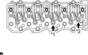
Text in Illustration *1 No. 3 Intake Valve *2 No. 4 Exhaust Valve Check the valve clearance of the No. 3 cylinder intake valve and the No. 4 cylinder exhaust valve.
Standard valve clearance (Cold) Intake 0.30 mm (0.0118 in.) Exhaust 0.45 mm (0.0177 in.) Note
Do not apply excessive force to the valve adjusting screw.
Tech Tips
If the clearance is not as specified, record the out-of-specification measurement, then adjust the valve clearance.
-
-
ADJUST VALVE CLEARANCE
-
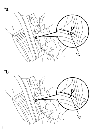
Text in Illustration *a TDC of No. 1 and No. 4 Cylinder *b TDC of No. 2 and No. 3 Cylinder *c Timing Mark Turn the crankshaft clockwise to align the timing mark on the crankshaft pulley with the pointer on the timing gear case.
-
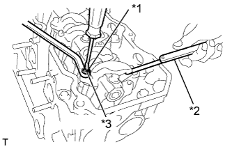
Text in Illustration *1 Adjusting Screw *2 Feeler Gauge *3 Lock Nut With each piston positioned at TDC on the compression stroke, using a feeler gauge, adjust each valve clearance.
Standard valve clearance (Cold) Intake 0.30 mm (0.0118 in.) Exhaust 0.45 mm (0.0177 in.) Tech Tips
The feeler gauge should move with a very slight pull.
-
Loosen the lock nut on the valve rocker arm and loosen the adjusting screw.
-
Insert a 0.30 mm (0.0118 in.) feeler gauge for the intake valve or a 0.45 mm (0.0177 in.) feeler gauge for the exhaust valve between the adjusting screw on the valve rocker arm and the valve bridge.
-
Turn the adjusting screw on the valve rocker arm until the feeler gauge slides with a very slight drag, and lock the adjusting screw with the lock nut.
- Torque:
- 29 N*m { 296 kgf*cm, 21 ft.*lbf }
-
-
INSTALL INJECTOR ASSEMBLY
Tech Tips
-
BLEED AIR FROM FUEL SYSTEM
-
Connect the drain hose to the air bleed plug.
-
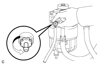
Loosen the fuel filter's air bleed plug.
Note
-
Do not use any tools.
-
Do not allow any fuel to spill.
-
If any fuel spills on any part of the engine, wipe it clean with a piece of cloth.
-
-
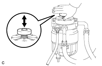
While covering the drain hose with a piece of cloth, press and release the priming pump until the fuel from the drain hose does not have any bubbles.
-
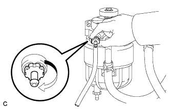
Tighten the air bleed plug.
Note
Do not use any tools.
-
-
INSPECT FOR FUEL LEAK
-
Perform the Active Test.
-
Connect the intelligent tester to the DLC3.
-
Start the engine.
-
Turn the intelligent tester on.
-
Enter the following menus: Powertrain / Engine and ECT / Active Test.
-
Perform the Active Test.
Intelligent Tester Display Test Details Control Range Diagnostic Notes Test the Fuel Leak Pressurizes common rail internal fuel pressure, and checks for fuel leaks Stop or Start
-
Fuel pressure inside common rail is pressurized to specified value and engine speed is increased to 2000 rpm when Start is selected.
-
Above conditions preserved while Start is selected.
-
-
-