ENGINE ON-VEHICLE INSPECTION

-
INSPECT ENGINE COOLANT
Tech Tips
-
INSPECT ENGINE OIL
Tech Tips
-
INSPECT BATTERY
Tech Tips
-
INSPECT AIR CLEANER FILTER ELEMENT SUB-ASSEMBLY
-
Remove the air cleaner filter element sub-assembly.
-
Visually check that the air cleaner filter is not excessively damaged or oily. If necessary, replace the air cleaner filter.
Tech Tips
-
If there is any dirt or a blockage in the air cleaner filter element sub-assembly, clean it with compressed air.
-
If any dirt or a blockage remains even after cleaning the air cleaner filter element sub-assembly with compressed air, replace it.
-
-
Install the air cleaner filter element sub-assembly.
-
-
INSPECT DRIVE BELT
-
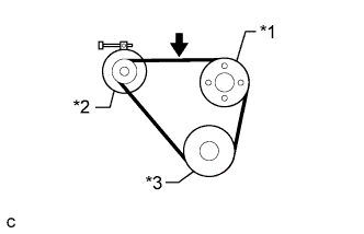
Text in Illustration *1 Fan Pulley *2 Generator *3 Crankshaft Pulley Check the fan and generator V belt deflection.
Tech Tips
-
The specified deflection values per belt are shown in the following table.
-
When inspecting the V belt deflection, apply 98 N (10 kgf, 22 lbf) tensile force to it.
Deflection Item Specified Condition New belt 10.5 to 12.5 mm (0.413 to 0.492 in.) Used belt 12.5 to 16.0 mm (0.492 to 0.630 in.) Note
-
Check the V belt deflection at the specified point.
-
When inspecting a belt which has been used for over 5 minutes, apply the used belt specifications.
-
-
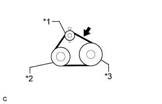
Text in Illustration *1 Idler Pulley *2 A/C Compressor *3 Crankshaft Pulley Check the No. 1 V (cooler compressor to crankshaft pulley) belt deflection (w/ Air Conditioning System).
Tech Tips
-
The specified deflection values per belt are shown in the following table.
-
When inspecting the V belt deflection, apply 98 N (10 kgf, 22 lbf) tensile force to it.
Deflection Item Specified Condition New belt 8.5 to 10.0 mm (0.335 to 0.394 in.) Used belt 10.0 to 12.0 mm (0.394 to 0.472 in.) Note
-
Check the V belt deflection at the specified point.
-
When inspecting a belt which has been used for over 5 minutes, apply the used belt specifications.
-
-
-
CHECK IDLE SPEED AND MAXIMUM SPEED
Note
Turn all the electrical systems and the A/C off.
-
Warm up and stop the engine.
-
Connect the intelligent tester to the DLC3.
-
Turn the ignition switch to ON.
-
Enter the following menus: Powertrain / Engine and ECT / Data List
Tech Tips
Refer to the intelligent tester operator's manual for further information regarding the selection of Data List.
-
Inspect the engine idle speed.
Standard idle speed 600 to 700 rpm -
Fully depress the accelerator pedal.
-
Check the maximum speed.
Maximum speed 3600 to 3700 rpm -
Turn the ignition switch off.
-
Disconnect the intelligent tester from the DLC3.
-
-
INSPECT COMPRESSION
-
Warm up and stop the engine.
-
Remove the 4 bolts from the glow plug hole.
-
Remove the oil filler cap.
-
Remove the 2 bolts, then remove the No. 2 cylinder head cover sub-assembly.
-
Disconnect all connectors from the 4 injectors.
-
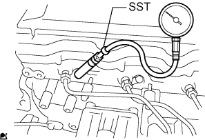
Install SST into the glow plug hole.
- SST
- 09992-00026
-
Connect a compression gauge to SST.
-
While cranking the engine, measure the compression pressure.
Standard compression pressure 3200 kPa (32.6 kgf/cm2, 464 psi) Minimum compression pressure 2700 kPa (27.5 kgf/cm2, 392 psi) Maximum difference between each cylinder 290 kPa (3.0 kgf/cm2, 42 psi) Note
-
Use a fully-charged battery so that the engine speed can be increased to 250 rpm or more.
-
Inspect the other cylinders in the same way.
-
Measure the compression pressure in as short a time as possible.
If the cylinder compression is low, pour a small amount of engine oil into the cylinder through the glow plug hole, then inspect it again.
Tech Tips
-
If adding oil increases the compression, the piston rings and/or cylinder bore may be worn or damaged.
-
If the pressure stays low, a valve may be stuck or seated improperly, or there may be leakage from the head gasket.
-
-
Remove the compression gauge and SST.
-
Disconnect the cable from the negative battery terminal.
-
Connect all connectors to the 4 injectors.
-
Install the No. 2 cylinder head cover sub-assembly with the 2 bolts.
- Torque:
- 29 N*m { 290 kgf*cm, 21 ft.*lbf }
-
Install the 4 bolts to the glow plug hole.
- Torque:
- 23 N*m { 229 kgf*cm, 17 ft.*lbf }
-
-
INSPECT DIESEL SMOKE
Standard value (Black smoke) 10% or less