CYLINDER HEAD INSPECTION

-
INSPECT CYLINDER HEAD SUB-ASSEMBLY
-
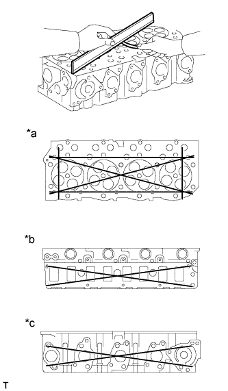
Text in Illustration *a Cylinder Block Side *b Intake Manifold Side *c Exhaust Manifold Side Using a straightedge and feeler gauge, measure the warpage on the cylinder block side and the intake manifold side and exhaust manifold side.
Maximum warpage 0.10 mm (0.00394 in.) If the warpage is more than the maximum, replace the cylinder head sub-assembly.
-
Using a dye penetrant, check the cylinder head sub-assembly for cracks.
If there are cracks, replace the cylinder head sub-assembly.
-
-
INSPECT INNER COMPRESSION SPRING
-
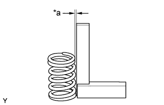
Text in Illustration *a Deviation Using a steel square, measure the deviation of the inner compression spring.
Maximum deviation 2.0 mm (0.0787 in.) If the deviation is more than the maximum, replace the inner compression spring.
-
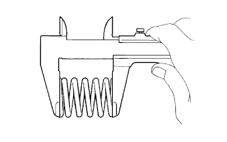
Using a vernier caliper, measure the free length of the inner compression spring.
Standard free length 85.1 mm (3.350 in.) Minimum free length 82.1 mm (3.232 in.) If the free length is less than the minimum, replace the inner compression spring.
-
-
INSPECT INTAKE VALVE
-
Visually check the valves for damage, burns, carbon or warpage, and check the valve heads, valve stems and valve stem grooves for cracks.
If excessive wear, burns, warpage or cracks are present, replace the intake valves.
-
Check the valve seating condition.
-
Lightly apply Prussian blue marking compound to the valve face.
-
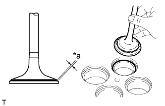
Text in Illustration *a Width Press the valve against the seat and check the seating condition.
Standard width 1.24 mm (0.0488 in.) or more If the Prussian blue mark does not appear 360° around the valve seat or the compound is scattered all around the valve face or seat, repair the valve face or the valve seat.
-
-
Using a vernier caliper, measure the overall length of the intake valve.
Standard overall length 129.8 mm (5.1102 in.) If the overall length is not as specified, replace the intake valve.
-
Using a micrometer, measure the diameter of the valve stem.
Standard valve stem diameter 6.957 to 6.972 mm (0.2739 to 0.2745 in.)
-
-
INSPECT EXHAUST VALVE
-
Visually check the valves for damage, burns, carbon or warpage. Check the valve heads, valve stems and valve stem grooves for cracks.
If excessive wear, burns, warpage or cracks are present, replace the exhaust valves.
-
Check the valve seating condition.
-
Lightly apply Prussian blue marking compound to the valve face.
-

Text in Illustration *a Width Press the valve against the seat and check the seating condition.
Standard width 1.24 mm (0.0488 in.) or more If the Prussian blue mark does not appear 360° around the valve seat or the compound is scattered all around the valve face or seat, repair the valve face or the valve seat.
-
-
Using a vernier caliper, measure the overall length of the exhaust valve.
Standard overall length 128.8 mm (5.0709 in.) If the overall length is not as specified, replace the exhaust valve.
-
Using a micrometer, measure the diameter of the valve stem.
Standard valve stem diameter 6.932 to 6.947 mm (0.2729 to 0.2735 in.)
-
-
INSPECT VALVE GUIDE BUSH OIL CLEARANCE
-
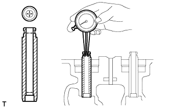
Using a caliper gauge, measure the internal diameter of the valve guide bush.
Standard inside diameter 7.000 to 7.015 mm (0.2756 to 0.2762 in.) If the bore diameter is not as specified, replace the valve guide bush.
-
Subtract the valve stem diameter measurement from the bore diameter measurement of the valve guide bush to calculate the oil clearance.
Standard Oil Clearance Item Specified Condition Intake 0.028 to 0.058 mm (0.00110 to 0.00228 in.) Exhaust 0.053 to 0.083 mm (0.00209 to 0.00327 in.) Maximum Oil Clearance Item Specified Condition Intake 0.12 mm (0.00472 in.) Exhaust 0.15 mm (0.00591 in.) If the oil clearance is more than the maximum, replace the valve and valve guide bush.
-
-
INSPECT INTAKE VALVE SINK
-
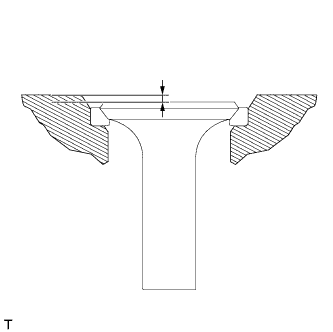
Using a vernier caliper, measure the intake valve sink.
Standard valve sink 0.8 to 1.0 mm (0.0315 to 0.0394 in.) Maximum valve sink 1.1 mm (0.0433 in.) If the sink is more than the maximum, replace the intake valve and intake valve seat.
Note
-
If the valve heads are protruding from the cylinder head surface, the valve heads may hit the pistons when the engine is running.
-
When replacing the intake valve and intake valve seat, always recheck the seating condition.
-
-
-
INSPECT EXHAUST VALVE SINK
-
Using a vernier caliper, measure the valve sink.
Standard valve sink 1.8 to 2.0 mm (0.0709 to 0.0787 in.) Maximum valve sink 2.1 mm (0.0827 in.) If the sink is more than the maximum, replace the exhaust valve and exhaust valve seat.
Note
-
If the valve heads are protruding from the cylinder head surface, the valve heads may hit the pistons when the engine is running.
-
When replacing the exhaust valve and exhaust valve seat, always recheck the seating condition.
-
-