CYLINDER BLOCK DISASSEMBLY

-
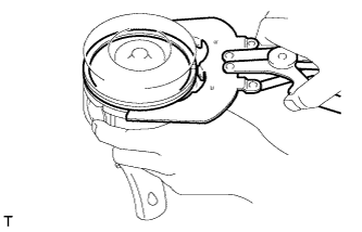
REMOVE PISTON WITH CONNECTING ROD
-
Remove the piston with connecting rod from the cylinder block.
-
-
REMOVE CONNECTING ROD BEARING
-
REMOVE CYLINDER LINER
Tech Tips
Before removing the cylinder liner, put matchmarks on the cylinder liner and cylinder block.
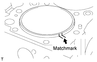
Note
When reusing the cylinder liner, misalignment with the cylinder block may concentrate stress on the thin part of the cylinder liner and the cylinder liner may break.
-
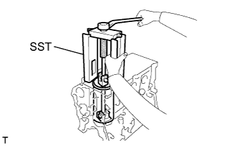
Using SST, remove the cylinder liner.
- SST
- S0942-01460
Tech Tips
Organize the parts so that each part location can be remembered for reassembly.
-
-
REMOVE CRANKSHAFT ASSEMBLY
-
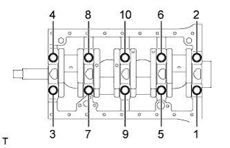
Remove the 10 bearing cap bolts in the order shown in the illustration.
-
Using a plastic-faced hammer, tap the bearing caps to remove them.
Note
Be careful not to damage the thrust washers and bearings.
-
Remove the crankshaft.
-
-
REMOVE CRANKSHAFT THRUST WASHER SET
Tech Tips
Organize the parts so that each part location can be remembered for reassembly.
-
REMOVE CRANKSHAFT BEARING SET
Tech Tips
Organize the parts so that each part location can be remembered for reassembly.
-
REMOVE REAR CYLINDER BLOCK COVER
-
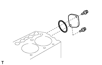
Remove the 2 bolts and rear cylinder block cover with O-ring.
-
-
REMOVE NO. 1 OIL NOZZLE SUB-ASSEMBLY
-
Remove the bolt and the No. 1 oil nozzle.
-
-
REMOVE PISTON RING SET
-
Using a piston ring expander, remove the piston rings.
Tech Tips
Arrange the piston rings in the correct order.
-
-
REMOVE PISTON PIN HOLE SNAP RING
-
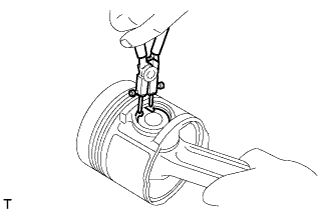
Using snap ring pliers, remove the snap rings.
-
-
REMOVE PISTON
-
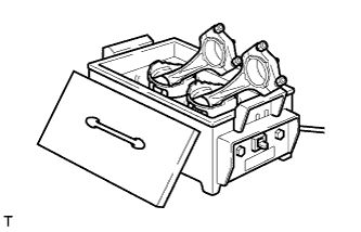
Gradually heat the piston to approximately 50°C (122°F).
-
Using a plastic-faced hammer and brass bar, lightly tap out the piston pin and remove the connecting rod.
Note
Arrange the pistons, pins, rings, connecting rods and bearings in the correct order.
-
-
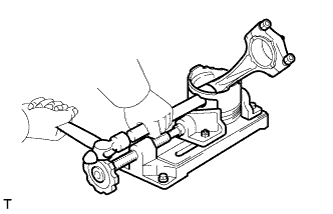
REMOVE CONNECTING ROD SMALL END BUSH
-
Prepare SST.
- SST
- S0940-21450
- S0948-11130
- S9233-10360
-
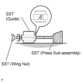
Assemble the guide and press sub-assembly by inserting its pin into the guide, then secure them with the wing nut.
Tech Tips
Orient the letter W stamped on the guide above the pin.
-
Make sure to align both supporting surfaces of the guide and press sub-assembly flatly on an even plane.
-
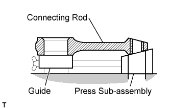
Using SST, remove the bush.
-
Set the connecting rod assembled without the crankshaft bearing on the guide and press sub-assembly.
-
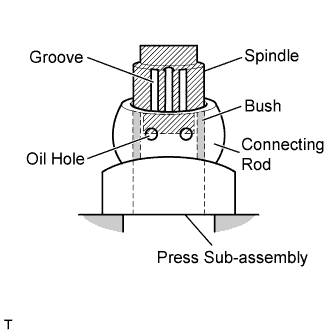
Using SST, install the spindle into the bush.
- SST
- S0940-21470
Tech Tips
Align the groove of the spindle with the oil hole of the bush.
-
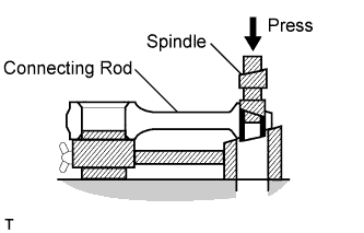
Using a press, remove the bush.
Tech Tips
Always operate the press slowly and smoothly.
-
-
-
REMOVE CAMSHAFT BEARING
-
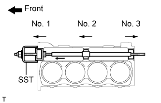
Using SST, remove the camshaft bearings in the directions indicated by the arrow marks in the illustration.
- SST
- 09215-00101 ( 09215-00130, 09215-00141, 09215-00150, 09215-00161 )
- 09215-00013 ( 09215-00021, 09215-00461 )
Note
Remove the No. 1, No. 2 and No. 3 camshaft bearings in order.
-