CYLINDER HEAD REPLACEMENT

-
REPLACE INTAKE VALVE SEAT
-
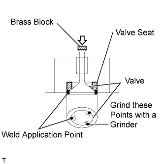
As shown in the illustration, grind the 3 points on the circumference of an unneeded valve and weld it to the valve seat.
Note
To protect the lower surface of the cylinder head from welding spatters, be sure to apply grease to the cylinder head before welding.
-
Place a brass block on the top of the valve stem and strike it with a hammer to remove the valve seat.
CAUTION:
When striking, metal shards may fly off on impact. Wear safety glasses to protect your eyes.
-
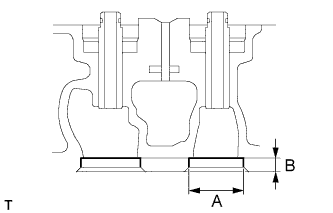
Using a caliper gauge and vernier calipers, measure the dimensions of the valve seat installation holes.
Intake valve seat dimensions A 36.00 to 36.015 mm (1.4173 to 1.4179 in.) B 8.4 to 8.6 mm (0.3307 to 0.3386 in.) If the result is not specified, replace the cylinder head.
-
Heat the cylinder head up to 80 to 100°C (176 to 212°F).
-
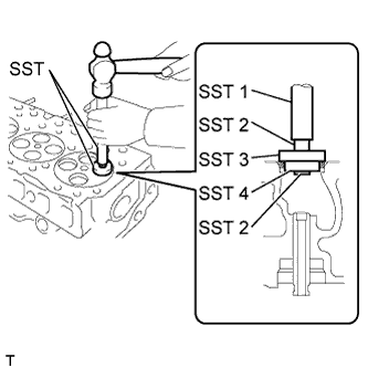
Using SST and a hammer, lightly tap new valve seats into the cylinder head.
- SST
- 09950-60010 ( 09951-00300, 09951-00360, 09952-06010 )
- 09950-70010 ( 09951-07100 )
SST 1 09951-07100 SST 2 09952-06010 SST 3 09951-00360 SST 4 09951-00300 -
Using SST and a hammer, completely tap in the valve seats.
- SST
- 09950-60010 ( 09951-00300, 09951-00360, 09952-06010 )
- 09950-70010 ( 09951-07100 )
-
-
REPLACE EXHAUST VALVE SEAT
-
As shown in the illustration, grind the 3 points on the circumference of an unneeded valve and weld it to the valve seat.
Note
To protect the lower surface of the cylinder head from welding spatters, be sure to apply grease to the cylinder head before welding.
-
Place a brass block on the top of the valve stem and strike it with a hammer to remove the valve seat.
CAUTION:
When striking, metal shards may fly off on impact. Wear safety glasses to protect your eyes.
-
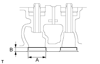
Using a caliper gauge and vernier calipers, measure the dimensions of the valve seat installation holes.
Exhaust valve seat dimensions A 36.00 to 36.015 mm (1.4173 to 1.4179 in.) B 8.4 to 8.6 mm (0.3307 to 0.3386 in.) If the result is not specified, replace the cylinder head.
-
Heat the cylinder head up to 80 to 100°C (176 to 212°F).
-
Using SST and a hammer, lightly tap new valve seats into the cylinder head.
- SST
- 09950-60010 ( 09951-00250, 09951-00320, 09952-06010 )
- 09950-70010 ( 09951-07100 )
SST 1 09951-07100 SST 2 09952-06010 SST 3 09951-00360 SST 4 09951-00300 -
Using SST and a hammer, completely tap in the valve seats.
- SST
- 09950-60010 ( 09951-00250, 09951-00320, 09952-06010 )
- 09950-70010 ( 09951-07100 )
-
-
REPLACE INTAKE VALVE GUIDE BUSH
-
Heat the cylinder head up to 80 to 100°C (176 to 212°F).
-
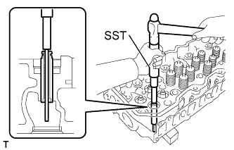
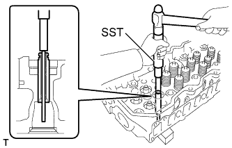
Using SST and a hammer, tap the valve guide bush.
- SST
- 09201-10000 ( 09201-01070 )
- 09950-70010 ( 09951-07100 )
-
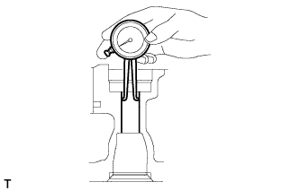
Using a caliper gauge, measure the inside diameter of the guide bush.
Bush inside diameter 13.000 to 13.018 mm (0.5118 to 0.5125 in.) Tech Tips
If the bush bore diameter of the cylinder head is greater than 13.02 mm (0.5125 in.), replace the cylinder head.
-
Heat the cylinder head up to 80 to 100°C (176 to 212°F).
-
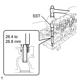
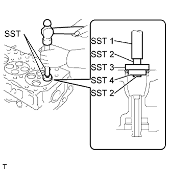
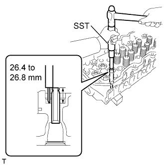
Using SST, tap in a new valve guide bush to the specified protrusion height.
- SST
- 09201-10000 ( 09201-01070 )
- 09950-70010 ( 09951-07100 )
Protrusion height 26.4 to 26.8 mm (1.039 to 1.055 in.) Note
Do not tap in the guide bush excessively.
-
Using a reamer, ream the inside of the valve guide bush to the specified oil clearance between the valve guide bush and valve stem.
Standard oil clearance 0.014 to 0.029 mm (0.0006 to 0.0011 in.) Maximum oil clearance 0.12 mm (0.0047 in.)
-
-
REPLACE EXHAUST VALVE GUIDE BUSH
-
Heat the cylinder head up to 80 to 100°C (176 to 212°F).
-
Using SST and a hammer, tap the valve guide bush.
- SST
- 09201-10000 ( 09201-01070 )
- 09950-70010 ( 09951-07100 )
-
Using a caliper gauge, measure the inside diameter of the guide bush.
Bush inside diameter 13.000 to 13.018 mm (0.5118 to 0.5125 in.) Tech Tips
If the bush bore diameter of the cylinder head is greater than 13.02 mm (0.5125 in.), replace the cylinder head.
-
Heat the cylinder head up to 80 to 100°C (176 to 212°F).
-
Using SST, tap in a new valve guide bush to the specified protrusion height.
- SST
- 09201-10000 ( 09201-01070 )
- 09950-70010 ( 09951-07100 )
Protrusion height 26.4 to 26.8 mm (1.039 to 1.055 in.) Note
Do not tap in the guide bush excessively.
-
Using a reamer, ream the inside of the valve guide bush to the specified oil clearance between the valve guide bush and valve stem.
Standard oil clearance 0.053 to 0.083 mm (0.0021 to 0.0033 in.) Maximum oil clearance 0.15 mm (0.0059 in.)
-
-
REPLACE INJECTION NOZZLE SEAT
-
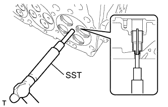
Using SST, remove the injection nozzle seat.
- SST
- 09201-10000 ( 09201-01050 )
- 09950-70010 ( 09951-07100 )
-
Remove the O-ring from the cylinder head sub-assembly.
-
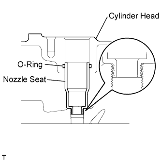
Apply a light coat of engine oil to new O-rings, and install them into the cylinder head.
Note
Be sure to install new O-rings. Reusing O-rings may cause water or gas leakage and lead to overheating or a cracked cylinder head.
-
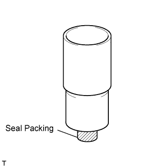
Apply seal packing to new nozzle seats.
Seal packing Toyota Genuine Seal Packing Black, Three Bond 1207B or equivalent Note
-
Remove any oil from the installation surface of the cylinder head and nozzle seats.
-
Be sure to install new nozzle seats. Reusing nozzle seats may cause water or gas leakage and lead to overheating or a cracked cylinder head.
-
-
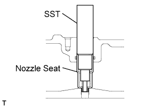
Using SST, install the nozzle seat onto the cylinder head.
- SST
- 09260-69015
- 09268-06020
-
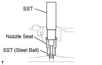
Using SST, stake the nozzle seat.
- SST
- 09260-69015
- 09268-06010
Note
Put a container under the cylinder head to prevent the steel ball from being lost.
-
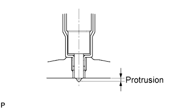
Install the injectors onto the cylinder head. Using vernier calipers, measure the protrusion of the injectors from the lower surface of the cylinder head.
Standard 2.45 to 2.95 mm (0.0964 to 0.1161 in.)
-
-
REPLACE STUD BOLT
-
Using "TORX" socket wrench E8 and E10, remove the stud bolts.
-
Using "TORX" socket wrench E8 and E10, install the stud bolts.
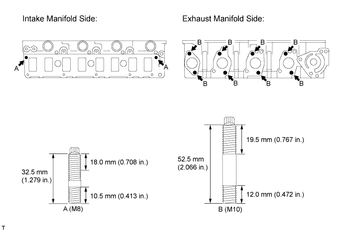
- Torque:
- Bolt A
- 25 N*m { 255 kgf*cm, 18 ft.*lbf }
- Bolt B
- 51 N*m { 520 kgf*cm, 38 ft.*lbf }
-