CAMSHAFT INSTALLATION

-
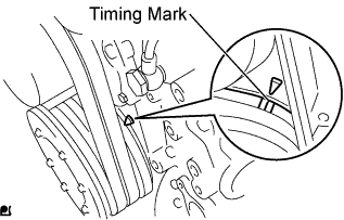
INSTALL CAMSHAFT
-
Apply engine oil to the camshaft journal and bearing.
-
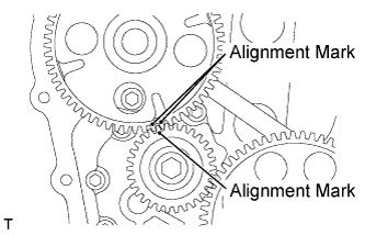
Align the matchmarks of the camshaft timing gear and oil pump gear and install the camshaft.
-
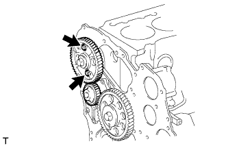
Install the camshaft with the 2 bolts.
- Torque:
- 29 N*m { 290 kgf*cm, 21 ft.*lbf }
-
-
INSTALL TIMING CHAIN OR BELT COVER OIL SEAL
-
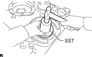
Using SST and a hammer, tap in the oil seal to the timing gear case so that the oil seal is flush with the timing gear edge.
- SST
- 09223-78010
Note
-
Be careful not to tap the oil seal at an angle.
-
Keep the gap between the gear case edge and the oil seal free of foreign matter.
-
Apply MP grease to the oil seal lip.
-
-
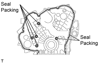
INSTALL TIMING GEAR CASE
-
Remove any oil packing material from the contact surface.
-
Apply seal packing in a continuous line (width: 3 to 4 mm (0.11 to 0.15 in.)) as shown in the illustration.
Seal packing Toyota Genuine Seal Packing Black, Three Bond 1207B or equivalent Note
-
Remove any oil from the contact surface.
-
Install the belt cover within 3 minutes of applying the seal packing.
-
Do not expose the seal packing to engine oil for at least 2 hours after installing.
-
-

Install the timing gear case with the 15 bolts.
- Torque:
- 29 N*m { 290 kgf*cm, 21 ft.*lbf }
-
-
INSTALL OIL PAN SUB-ASSEMBLY
-
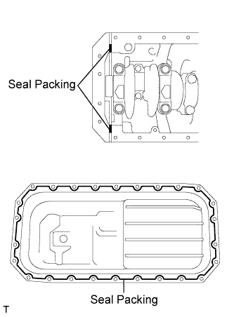
Remove any oil packing material from the contact surface.
-
Apply seal packing in a continuous line (width: 3 to 4 mm (0.11 to 0.15 in.)) as shown in the illustration.
Seal packing Toyota Genuine Seal Packing Black, Three Bond 1207B or equivalent Note
-
Remove any oil from the contact surface.
-
Install the oil pan within 3 minutes of applying the seal packing.
-
Do not expose the seal packing to engine oil for at least 2 hours after installing.
-
-
Install the oil pan with the 26 bolts.
- Torque:
- 29 N*m { 290 kgf*cm, 21 ft.*lbf }
-
-
INSTALL FLYWHEEL HOUSING STAY LH
-
Install the flywheel housing stay LH with the 4 bolts.
- Torque:
- for M14 bolt
- 132 N*m { 1350 kgf*cm, 97 ft.*lbf }
- for M12 bolt
- 97 N*m { 990 kgf*cm, 72 ft.*lbf }
-
-
INSTALL FLYWHEEL HOUSING STAY RH
-
Install the flywheel housing stay RH with the 4 bolts.
- Torque:
- for M14 bolt
- 132 N*m { 1350 kgf*cm, 97 ft.*lbf }
- for M12 bolt
- 97 N*m { 990 kgf*cm, 72 ft.*lbf }
-
-
INSTALL CRANKSHAFT PULLEY
-
Install the pulley and spacer to the crankshaft.
Tech Tips
Align the pulley set key with the key groove of the pulley.
-
Using a 46 mm socket wrench, tighten the nut.
- Torque:
- 515 N*m { 5252 kgf*cm, 380 ft.*lbf }
Tech Tips
Insert a screwdriver through the inspection hole of the flywheel housing into the ring gear of the flywheel to keep it from turning together with the crankshaft.
-
-
INSTALL SUPPLY PUMP ASSEMBLY
-
Install a new O-ring onto the timer cover.
-
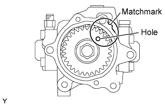
Turn the drive gear and align the hole with the matchmark as shown in the illustration.
-
Check the No. 1 cylinder to TDC/compression.
-
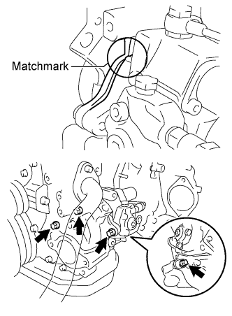
Align the matchmarks of the timer cover and the front end plate, and then install the supply pump assembly with the 4 bolts.
- Torque:
- 29 N*m { 291 kgf*cm, 21 ft.*lbf }
-
When the crankshaft position sensor's installation hole can be accessed directly:
-
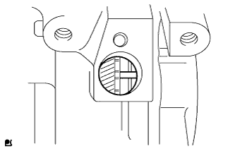
Check that the knock pin of the injection pump drive gear is at the center of the hole. If not, perform steps (b), (c), and (d) again. Then, proceed to step (g).
-
-
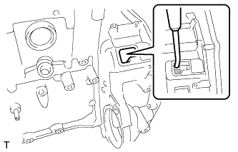
When the crankshaft position sensor's installation hole cannot be accessed directly:
-
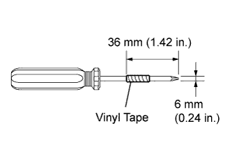
Tape the screwdriver as shown in the illustration.
-
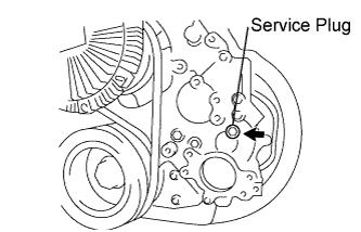
Remove the service plug and gasket from the timing chain cover sub-assembly.
-
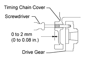
Insert the screwdriver into the service plug hole.
-
Check that the tape end and timing chain cover sub-assembly are aligned as shown in the illustration. If not, perform steps (b) and (c) again.
-
Install the service plug and gasket to the timing chain cover sub-assembly.
-
-
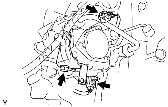
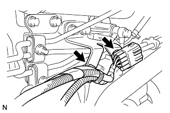
Install the holder clip with the bolt.
- Torque:
- 29 N*m { 291 kgf*cm, 21 ft.*lbf }
-
Connect the 2 connectors.
-
-
INSTALL FUEL RETURN PIPE SUB-ASSEMBLY
-

Temporarily install the fuel return pipe sub-assembly with the 2 union bolts and 5 new gaskets.
-
Tighten the 2 union bolts.
- Torque:
- 20 N*m { 200 kgf*cm, 15 ft.*lbf }
-
-
INSTALL COMMON RAIL ASSEMBLY
-

Install the common rail assembly with the 2 bolts.
- Torque:
- 55 N*m { 560 kgf*cm, 41 ft.*lbf }
-
Connect the fuel hose and tighten the clip.
-
Connect the fuel pressure sensor connector.
-
-
INSTALL NO. 3 NOZZLE LEAKAGE PIPE SUB-ASSEMBLY
-
Install 4 new gaskets and the No. 3 nozzle leakage pipe with the 2 union bolts.
- Torque:
- 13 N*m { 130 kgf*cm, 10 ft.*lbf }
-
Install the fuel pipe clamp with the nut. Tighten the nut until the clamp's edge makes contact with the engine side clamp's edge.
-
-
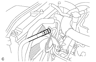
INSTALL FUEL FILTER TO INJECTION PUMP FUEL PIPE
-
Using a union nut wrench (17 mm), install the fuel filter to injection pump fuel pipe with the 2 union nuts.
- Torque:
- 35 N*m { 360 kgf*cm, 26 ft.*lbf }
Note
-
If the supply pump assembly has been replaced, the fuel filter to injection pump fuel pipe must also be replaced.
-
Refer to the torque above when not using SST. When using SST, calculate the torque in accordance with the lengths of SST and the torque wrench Click here.
-
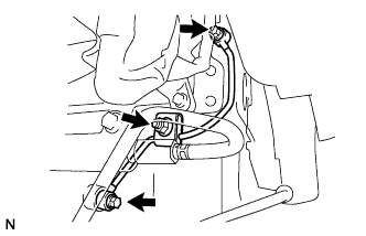
Install the fuel pipe clamp with the nut. Tighten the nut until the clamp edge makes contact with the engine side clamp edge.
-
Connect the 2 wire harness clamps.
-
Connect the wire harness connector.
-
-
INSTALL FUEL PIPE SUB-ASSEMBLY
-
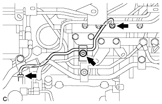
Install the fuel pipe sub-assembly with the union bolt and 2 new gaskets.
- Torque:
- 25 N*m { 250 kgf*cm, 18 ft.*lbf }
-
Install the 3 fuel pipe clamps with the 2 bolts and nut. Tighten the 2 bolts and nut until the clamp edges make contact with the engine side clamp edges.
-
-
INSTALL VACUUM PUMP ASSEMBLY
-

Install the vacuum pump assembly with a new O-ring and the 2 nuts.
- Torque:
- 55 N*m { 560 kgf*cm, 41 ft.*lbf }
-
-
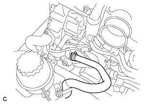
INSTALL VACUUM PUMP OIL PIPE SUB-ASSEMBLY
-
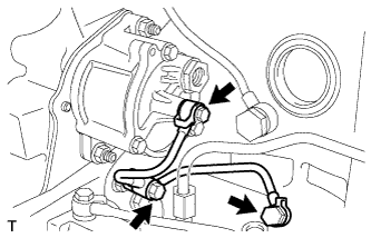
Install the vacuum pump oil pipe sub-assembly with a new gasket and the 3 union bolts.
- Torque:
- 13 N*m { 130 kgf*cm, 10 ft.*lbf }
-
-
INSTALL VACUUM PIPE
-
Install the vacuum pipe with 2 new gaskets, the union bolt, and the bolt.
- Torque:
- 13 N*m { 130 kgf*cm, 10 ft.*lbf }
-
-
INSTALL CAMSHAFT POSITION SENSOR
-
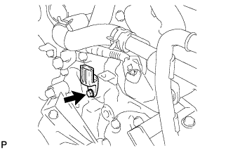
Install the camshaft position sensor with a new O-ring and the bolt.
- Torque:
- 12 N*m { 122 kgf*cm, 9 ft.*lbf }
-
-
INSTALL CRANKSHAFT POSITION SENSOR
-
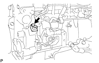
Install the crankshaft position sensor with a new O-ring and the bolt.
- Torque:
- 12 N*m { 122 kgf*cm, 9 ft.*lbf }
-
-
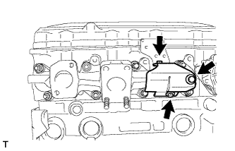
INSTALL EXHAUST MANIFOLD
-
Install 4 new gaskets to the cylinder head as shown in the illustration.
-
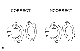
Temporarily install the exhaust manifold. Uniformly and temporarily tighten the 8 nuts and 8 spacers in the order shown in the illustration.
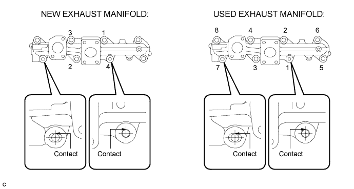
Tech Tips
The stud bolts should contact the exhaust manifold as shown in the illustration
-
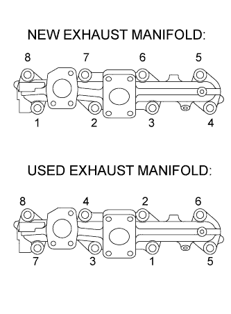
Tighten the 8 nuts in the order shown in the illustration.
- Torque:
- 59 N*m { 602 kgf*cm, 44 ft.*lbf }
-
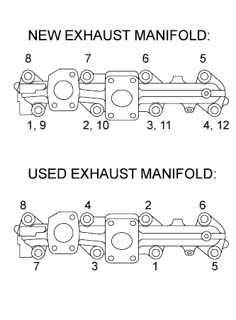
Tighten the 8 nuts in the order shown in the illustration.
- Torque:
- 59 N*m { 602 kgf*cm, 44 ft.*lbf }
-
Install the exhaust manifold heat insulator sub-assembly with the 3 bolts.
- Torque:
- 29 N*m { 290 kgf*cm, 21 ft.*lbf }
-
-
INSTALL INTAKE MANIFOLD
-
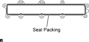
Apply seal packing in a continuous line (width: 1.5 to 2.5 mm (0.06 to 0.10 in.)) as shown in the illustration.
Seal packing Toyota Genuine Seal Packing Black, Three Bond 1207B or equivalent Note
-
Remove any oil from the contact surface.
-
Install the timing chain cover within 3 minutes, and tighten the bolts within 15 minutes of applying the seal packing.
-
-
Install the intake manifold with the 8 bolts and 2 nuts.
- Torque:
- 29 N*m { 290 kgf*cm, 21 ft.*lbf }
-
-
INSTALL WATER PUMP ASSEMBLY
-
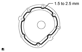
Apply a continuous bead of seal packing (diameter 1.5 to 2.5 mm (0.06 to 0.10 in.)) as shown in the illustration.
Seal packing Toyota Genuine Seal Packing Black, Three Bond 1207B or equivalent Note
-
Remove any oil from the contact surface.
-
Install the water pump within 3 minutes of applying the seal packing.
-
Do not start the engine for at least 2 hours after the installation.
-
-

Install the water pump assembly with the 8 bolts.
- Torque:
- 29 N*m { 290 kgf*cm, 21 ft.*lbf }
-
-
INSTALL VANE PUMP ASSEMBLY
-
Coat a new O-ring with power steering fluid and install it to the vane pump.
-
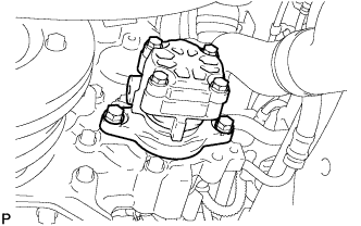
Install the vane pump assembly with the 2 bolts.
- Torque:
- 47 N*m { 480 kgf*cm, 35 ft.*lbf }
-
-
CONNECT PRESSURE FEED HOSE
-
Install the pressure feed hose with a new gasket.
-
Using a union nut wrench (19 mm), install the pressure feed hose.
- Torque:
- 44 N*m { 450 kgf*cm, 32 ft.*lbf }
-
-
CONNECT NO. 2 OIL RESERVOIR TO PUMP HOSE
-
Connect the No. 2 oil reservoir to pump hose.
-
-
INSTALL CYLINDER HEAD GASKET
Tech Tips
-
INSTALL NEGATIVE BATTERY TERMINAL
-
ADD ENGINE OIL
-
Add fresh oil and install the oil filler cap sub-assembly.
Engine oil Oil Grade Oil Viscosity (SAE)
-
API CD, CE, CF, CH-4, or CI-4 (May also use API CE, or CD.)
-
10W-30
-
20W-20
-
15W-40
-
30
-
40
Capacity Item Fill amount Drain and refill with oil filter change 7.1 liters (7.5 US qts, 6.2 Imp. qts) Drain and refill without oil filter change 5.9 liters (6.2 US qts, 5.2 Imp. qts) Dry fill 7.8 liters ( 8.3 US qts, 6.9 Imp. qts) -
-
-
ADD ENGINE COOLANT
-
Add engine coolant.
Specified capacity 14.7 liters (15.5 US qts, 12.9 Imp. qts) Note
Never use water as a substitute for engine coolant.
Tech Tips
-
TOYOTA vehicles are filled with TOYOTA SLLC at the factory. In order to avoid damage to the engine cooling system and other technical problems, only use TOYOTA SLLC or similar high quality ethylene glycol based non-silicate, non-amine, non-nitrite, non-borate coolant with long-life hybrid organic acid technology (coolant with long-life hybrid organic acid technology consists of a combination of low phosphates and organic acids).
-
Contact your TOYOTA dealer for further details.
-
-
Check the coolant level inside the radiator by squeezing the inlet and outlet radiator hoses several times by hand. If the coolant level goes down, add coolant.
-
Install the radiator cap.
-
Slowly pour coolant into the radiator reservoir until it reaches the FULL line.
-
Bleed air from the cooling system.
-
Warm up the engine until the thermostat opens.
While the thermostat is open, circulate the coolant for several minutes.
-
Press the inlet and outlet radiator hoses several times by hand to bleed air.
Note
-
Be careful as the radiator hoses are hot.
-
Keep your hands away from the radiator fan.
-
-
-
Stop the engine and wait until the coolant cools down.
-
Remove the radiator cap and check the coolant level.
-
If the coolant level has dropped, add coolant.
-
Check the coolant level inside the radiator reservoir tank again. If it is below the full level, add coolant.
-
-
ADD POWER STEERING FLUID
-
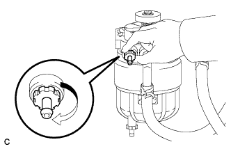
BLEED AIR FROM FUEL SYSTEM
-
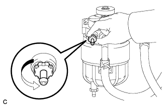
Loosen the fuel filter's air bleed plug.
Note
-
Do not use any tools.
-
Do not allow any fuel to spill.
-
If any fuel spills on any part of the engine, wipe it clean with a shop rag or a piece of cloth.
-
-
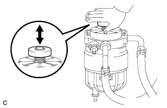
While covering the drain pipe with a shop rag or a piece of cloth, press and release the priming pump until the fuel from the drain pipe does not have any bubbles.
-
Tighten the air bleed plug.
Note
Do not use any tools.
-
-
INSPECT FOR ENGINE OIL LEAK
-
INSPECT FOR ENGINE COOLANT LEAK
-
Remove the radiator cap.
CAUTION:
Do not remove the radiator cap while the engine and radiator are still hot. Pressurized, hot engine coolant and steam may be released and cause serious burns.
-
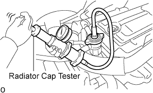
Fill the radiator with coolant and attach a radiator cap tester.
-
Warm up the engine.
-
Using a radiator cap tester, increase the pressure inside the radiator to 137 kPa (1.4 kgf/cm2, 19.9 psi), and check that the pressure does not drop.
If the pressure drops, check the hoses, radiator and water pump for leaks. If no external leaks are found, check the heater core, cylinder block and cylinder head.
-
Install the radiator cap.
-
-
BLEED POWER STEERING SYSTEM
-
INSPECT FOR POWER STEERING FLUID LEAK
-
INSPECT FOR EXHAUST GAS LEAK
-
INSPECT FOR FUEL LEAK
-
Perform the Active Test.
-
Connect the intelligent tester to the DLC3.
-
Start the engine.
-
Turn the intelligent tester on.
-
Select the following menu items: Powertrain / Engine / Active Test.
-
Perform the Active Test.
Intelligent Tester Display Test Details Control Range Diagnostic Notes Test the Fuel Leak Fuel leaks (common rail internal fuel pressure is raised) Stop/Start
-
Fuel pressure inside common rail pressurized to specified value and engine speed increased to 2000 rpm when Start is selected.
-
Above conditions preserved while Start is selected.
-
-
-
-
INSTALL ENGINE UNDER COVER