ENGINE ON-VEHICLE INSPECTION

-
INSPECT ENGINE COOLANT
-
Remove the radiator cap.
CAUTION:
Do not remove the radiator cap while the engine and radiator are still hot. Pressurized, hot engine coolant and steam may be released and cause serious burns.
-
Check if there are any excessive deposits of rust or scales around the radiator cap and radiator filler hole. Also, the coolant should be free of oil.
If excessively dirty, clean the coolant passage and replace the coolant.
-
Install the radiator cap.
-
-
INSPECT ENGINE OIL
-
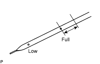
Warm up the engine, then stop the engine and wait 5 minutes. Check that the engine oil level is between the Low and Full level marks.
If low, check for leakage and add oil up to the full level mark.
Note
-
Do not add engine oil above the Full mark.
-
If the oil level is 25 mm (0.98 in.) above the Full mark, replace engine oil.
-
-
-
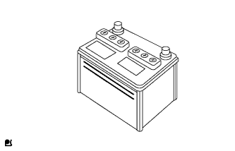
INSPECT BATTERY
-
Check the battery for damage and deformation. If severe damage, deformation or leakage is found, replace the battery.
-
Check the volume of electrolyte in each cell (for maintenance-free batteries).
-
If the electrolyte volume is below the lower line, add distilled water to each cell or replace the battery.
-
-
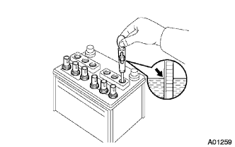
Check the volume of electrolyte in each cell (for non-maintenance-free batteries).
-
If the electrolyte volume is below the lower line, add distilled water to each cell. Then, recharge the battery and check the electrolyte specific gravity.
Standard electrolyte specific gravity 1.25 to 1.29 at 20°C (68°F) If the result is not as specified, recharge or replace the battery.
-
-
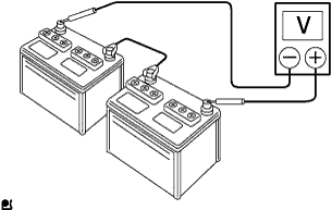
Measure the battery voltage.
-
If it has been less than 20 minutes since you stopped driving the vehicle or since the engine was stopped, turn the ignition switch and electrical systems (headlight, blower motor, rear defogger etc.) to the ON position for 20 seconds. This will remove the surface charge on the battery.
-
Turn the ignition switch off.
-
Turn the electrical systems to OFF.
-
Using a voltmeter, measure the battery voltage between the positive (+) and negative (-) terminals of the battery.
Standard voltage 24.0 to 25.0 V at 20°C (68°F) If the result is not as specified, recharge or replace the battery.
-
-
-
INSPECT AIR CLEANER FILTER ELEMENT SUB-ASSEMBLY
-
INSPECT DRIVE BELT
-
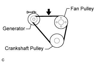
Check the V belt deflection.
Tech Tips
The specified deflection values per belt are shown in the following table.
Deflection Item Specified Condition New belt 10.5 to 12.5 mm (0.41 to 0.49 in ) Used belt 12.5 to 16.0 mm (0.49 to 0.63 in ) Note
-
Check the V belt deflection at the specified point.
-
When inspecting a belt which has been used for over 5 minutes, apply the used belt specifications.
-
-
-
CHECK TAPPET FOR ABNORMAL NOISE
-
CHECK IDLE SPEED AND MAXIMUM SPEED
Note
Turn all the electrical systems and the A/C OFF.
-
Warm up and stop the engine.
-
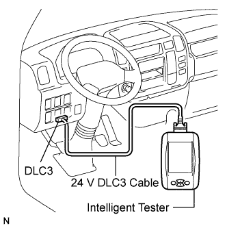
When using the intelligent tester:
-
(a) Replace the normal DLC3 cable (12 V specification) for the intelligent tester with the 24 V DLC3 cable.
Note
Be sure to use the 24 V DLC3 cable when connecting the intelligent tester to the DLC3. Using the normal DLC3 cable (12 V specification) will cause damage to the tester.
-
Connect the intelligent tester to the DLC3.
-
Turn the ignition switch to the ON position.
-
-
Select the following menu items: Powertrain / Engine and ECT / Data List
Tech Tips
Refer to the intelligent tester operator's manual for further information regarding the selection of Data List.
-
Inspect the engine idling speed.
Idling speed 550 to 650 rpm
-
-
Fully depress the accelerator pedal.
-
Check the maximum speed.
Maximum speed 3600 to 3700 rpm -
Turn the ignition switch off.
-
Disconnect the intelligent tester from the DLC3.
-
When not using the intelligent tester:
-
Install SST to terminal TAC of the DLC3, then connect a tachometer.
- SST
- 09843-18040
Note
Examine the terminal number before connecting SST. Connecting to the wrong terminal can damage the engine.
-
Turn the ignition switch to the ON position.
-
Inspect the engine idling speed.
Idling speed 550 to 650 rpm -
Fully depress the accelerator pedal.
-
Check the maximum speed.
Maximum speed 3600 to 3700 rpm -
Turn the ignition switch off.
-
Disconnect the tachometer.
-
Remove SST from terminal TAC.
-
-
-
INSPECT COMPRESSION
-
Warm up and stop the engine.
-
Remove the 4 bolts from the glow plug hole.
-
Remove the oil filler cap.
-
Remove the 2 bolts, then remove the No. 2 cylinder head cover sub-assembly.
-
Disconnect all connectors from the 4 injectors.
-
Crank the engine to remove foreign matter before measuring the compression.
-
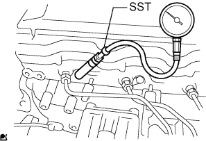
Install the SST into the glow plug hole.
- SST
- 09992-00025
-
Connect a compression gauge to SST.
- SST
- 09992-00025
-
While cranking the engine, measure the compression pressure.
Compression pressure 3200 kPa (33 kgf/cm2, 464 psi) Minimum pressure 2700 kPa (27 kgf/cm2, 392 psi) Difference between each cylinder 290 kPa (3 kgf/cm2, 42 psi) Note
-
Use a fully-charged battery so that the engine speed can be increased to 250 rpm or more.
-
Inspect the other cylinders in the same way.
-
Measure the compression pressure in as short a time as possible.
If the cylinder compression is low, pour a small amount of engine oil into the cylinder through the glow plug hole, then inspect it again.
Tech Tips
-
If adding oil increases the compression, the piston rings and/or cylinder bore may be worn or damaged.
-
If the pressure stays low, a valve may be stuck or seated improperly, or there may be leakage from the gasket.
-
-
Remove the compression gauge and SST.
-
Disconnect the cable from the negative battery terminal.
-
Connect all connectors to the 4 injectors.
-
Install the No. 2 cylinder head cover sub-assembly with the 2 bolts.
- Torque:
- 29 N*m { 290 kgf*cm, 21 ft.*lbf }
-
Install the 4 bolts to the glow plug hole.
- Torque:
- 23 N*m { 229 kgf*cm, 17 ft.*lbf }
-
-
INSPECT DIESEL SMOKE
Standard (Black smoke) 10% or less