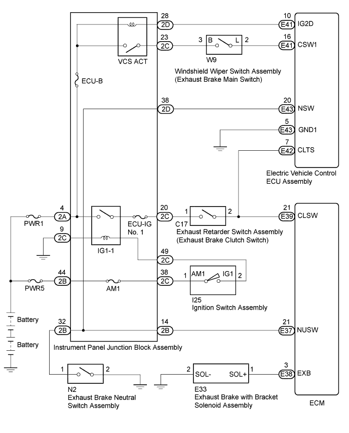
ECD SYSTEM Exhaust Brake System Circuit
WIRING DIAGRAM
INSPECTION PROCEDURE
Note
Inspect the fuses for circuits related to this system before performing the following inspection procedure.
Tech Tips
If the exhaust brake does not operate, perform the following inspection.
PROCEDURE
-
DTC OUTPUT
-
Replace the normal DLC3 cable (12 V specification) for the intelligent tester with the 24 V DLC3 cable.
Note
Be sure to use the 24 V DLC3 cable when connecting the intelligent tester to the DLC3. Using the normal DLC3 cable (12 V specification) will cause damage to the tester.
-
Connect the intelligent tester to the DLC3.
-
Turn the ignition switch to ON.
-
Turn the tester on.
-
Enter the following menus: Powertrain / Engine and ECT / DTC.
-
Read the DTCs.
Tech Tips
It may be the case that exhaust brake system operation has been prohibited due to DTCs being stored.
Result Result Proceed to DTC is not output A DTC is output B
B 
GO TO DTC CHART Click here
A 
-
-
CHECK ECM
-
Turn the ignition switch to ON.
-
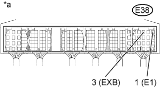
Text in Illustration *a Component with harness connected
(ECM)
Measure the voltage according to the value(s) in the table below.
Standard Voltage Tester Connection Condition Specified Condition E38-3 (EXB) - E38-1 (E1) Exhaust brake operating 18 to 27 V Tech Tips
Operating conditions for the exhaust brake:
-
The exhaust brake main switch is on.
-
The accelerator pedal is not being operated.
-
The vehicle is moving at a speed of 3 km/h or more.
-
The ABS is not operating.
-
NG 
CHECK ELECTRIC VEHICLE CONTROL ECU ASSEMBLY Click here
OK
-
-
CHECK EXHAUST BRAKE WITH BRACKET SOLENOID ASSEMBLY
-
Inspect the exhaust brake with bracket solenoid assembly Click here.
NG
REPLACE EXHAUST BRAKE WITH BRACKET SOLENOID ASSEMBLY
OK
-
-
CHECK EXHAUST RETARDER ASSEMBLY
-
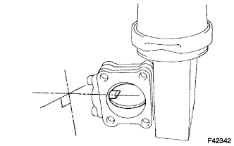
Remove the exhaust retarder assembly.
-
Check that the butterfly valve is perpendicular to the flange (completely open).
-
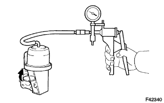
Using a vacuum pump, create a vacuum of approximately 67 kPa (503 mmHg, 19.8 in.Hg) in the exhaust brake chamber, and then check that the butterfly valve completely closes and the needle on the pump does not drop.
-
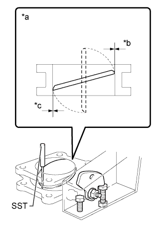
Text in Illustration *a Valve Cross-section (When viewed from the side with the lever) *b Point A *c Point B With the needle of the pump at the same position as the previous step, check the butterfly valve clearance.
OK 0.2 to 0.3 mm Result Result Proceed to OK A Butterfly valve does not completely open B Needle drops when vacuum is created C Needle does not drop when vacuum is created but clearance is not within standard range D Tech Tips
If the results of the inspection are normal, perform troubleshooting for black smoke. Skip over any steps which have already been performed and proceed from the next step Click here.
B
ADJUST OR REPLACE EXHAUST RETARDER ASSEMBLY
C
REPLACE EXHAUST RETARDER VACUUM CYLINDER ASSEMBLY
D
ADJUST EXHAUST RETARDER ASSEMBLY (CLEARANCE ADJUSTMENT)
A 
CHECK AND REPAIR OR REPLACE VACUUM RELATED PARTS (VACUUM HOSES, LINES)
-
-
CHECK ELECTRIC VEHICLE CONTROL ECU ASSEMBLY
-
Turn the ignition switch to ON.
-
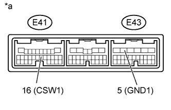
Text in Illustration *a Component with harness connected
(Electric Vehicle Control ECU Assembly)
Measure the voltage according to the value(s) in the table below.
Standard Voltage Tester Connection Condition Specified Condition E41-16 (CSW1) - E43-5 (GND1) IG ON
Exhaust brake main switch on
18 to 27 V IG ON
Exhaust brake main switch off
0 to 2 V
NG
INSPECT WINDSHIELD WIPER SWITCH ASSEMBLY Click here
OK
-
-
CHECK ECM
-
Turn the ignition switch to ON.
-
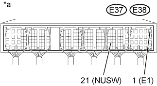
Text in Illustration *a Component with harness connected
(ECM)
Measure the voltage according to the value(s) in the table below.
Standard Voltage Tester Connection Condition Specified Condition E37-21 (NUSW) - E38-1 (E1) IG ON
Shift lever in neutral
18 to 27 V IG ON
Shift lever not in neutral
0 to 2 V
NG
INSPECT EXHAUST BRAKE NEUTRAL SWITCH ASSEMBLY Click here
OK
-
-
CHECK ELECTRIC VEHICLE CONTROL ECU ASSEMBLY
-
Turn the ignition switch to ON.
-
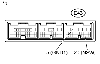
Text in Illustration *a Component with harness connected
(Electric Vehicle Control ECU Assembly)
Measure the voltage according to the value(s) in the table below.
Standard Voltage Tester Connection Condition Specified Condition E43-20 (NSW) - E43-5 (GND1) IG ON
Shift lever in neutral
18 to 27 V IG ON
Shift lever not in neutral
0 to 2 V
NG
INSPECT EXHAUST BRAKE NEUTRAL SWITCH ASSEMBLY Click here
OK
-
-
CHECK ECM
-
Turn the ignition switch to ON.
-
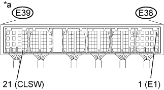
Text in Illustration *a Component with harness connected
(ECM)
Measure the voltage according to the value(s) in the table below.
Standard Voltage Tester Connection Condition Specified Condition E39-21 (CLSW) - E38-1 (E1) IG ON
Clutch pedal released
18 to 27 V IG ON
Clutch pedal depressed
0 to 2 V
NG
INSPECT EXHAUST RETARDER SWITCH ASSEMBLY Click here
OK
-
-
CHECK ELECTRIC VEHICLE CONTROL ECU ASSEMBLY
-
Turn the ignition switch to ON.
-
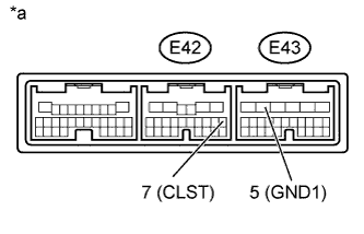
Text in Illustration *a Component with harness connected
(Electric Vehicle Control ECU Assembly)
Measure the voltage according to the value(s) in the table below.
Standard Voltage Tester Connection Condition Specified Condition E42-7 (CLTS) - E43-5 (GND1) IG ON
Clutch pedal released
18 to 27 V IG ON
Clutch pedal depressed
0 to 2 V
NG
INSPECT EXHAUST RETARDER SWITCH ASSEMBLY Click here
OK
-
-
REPLACE ECM
-
Replace the ECM Click here.
Note
After replacing the ECM, the new ECM needs registration Click here and initialization Click here.
NEXT
END
-
-
INSPECT EXHAUST BRAKE NEUTRAL SWITCH ASSEMBLY
-
Inspect the exhaust brake neutral switch assembly Click here.
NG
REPLACE EXHAUST BRAKE NEUTRAL SWITCH ASSEMBLY Click here
OK
REPAIR OR REPLACE HARNESS AND CONNECTOR
-
-
INSPECT EXHAUST RETARDER SWITCH ASSEMBLY
-
Inspect the exhaust retarder switch assembly Click here.
NG
REPLACE EXHAUST RETARDER SWITCH ASSEMBLY Click here
OK
REPAIR OR REPLACE HARNESS AND CONNECTOR
-
-
INSPECT WINDSHIELD WIPER SWITCH ASSEMBLY
-
Inspect the windshield wiper switch assembly Click here.
NG
REPLACE WINDSHIELD WIPER SWITCH ASSEMBLY Click here
OK
REPAIR OR REPLACE HARNESS AND CONNECTOR
-