ECD SYSTEM Clogging by DPF Catalytic Converter
DESCRIPTION
The differential pressure sensor is mounted on the exhaust pipe. It measures the pressure before and after the DPF catalytic converter (built into the center exhaust pipe assembly), converts the difference in pressure into a voltage signal, and outputs it to the ECM. Based on this signal, the ECM determines whether the DPF catalytic converter is clogged. If the DPF catalytic converter is clogged, the ECM activates the forcible regeneration function of the DPF catalytic converter. In some cases, the forcible regeneration function may not be conducted depending on the driving conditions. In such cases, the indicator light in the combination meter assembly and the DPF switch light blink to inform the driver that the converter is clogged. When the driver presses the DPF switch, the forcible regeneration function signal (RGSW) is transmitted to the ECM, and the forcible regeneration function starts. If the vehicle is driven continuously without performing the forcible regeneration function when the indicator lights are blinking, PM (Particulate Matter) accumulates and DTC P2463 is set. If the forcible regeneration function is activated when the amount of PM accumulation is too high, the temperature in the DPF catalytic converter rises beyond normal operating conditions (it may reach 800°C (1472°F) or higher) and the DPF catalytic converter may melt down. Therefore, if the forcible regeneration function is activated with DTC P2463 set, the differential pressure when the engine is running at near the maximum no-load speed (3350 rpm) must be checked. If the pressure exceeds the threshold, the DPF catalytic converter must be cleaned.
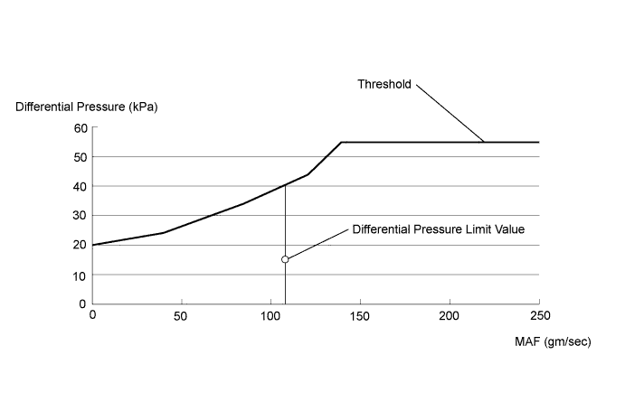
| Engine Speed | Standard Differential Pressure | MAF |
|---|---|---|
| 3300 to 3400 rpm | 15 kPa or less | 135 to 145 gm/sec |
INSPECTION PROCEDURE
Note
-
After replacing the ECM, the new ECM needs registration Click here and initialization Click here.
-
After replacing the injection or supply pump assembly, the ECM needs initialization Click here.
-
After replacing an injector assembly, the ECM needs registration Click here.
PROCEDURE
-
PERFORM ENGINE SPEED ACCELERATION
-
Warm up the engine.
-
Disconnect the cable from the negative (-) battery terminal and wait for at least 1 minute.
-
Reconnect the cable to the negative (-) battery terminal.
-
Initialize the learning values of the injection or supply pump assembly Click here.
Tech Tips
Perform initialization with the engine warmed up (engine coolant temperature 60°C (140°F) or more and fuel temperature 20°C (68°F) or more).
-
Initialize the leaning values of the diesel throttle body assembly Click here.
-
Accelerate the engine speed to the maximum speed with no load 20 times.
-
Check for black smoke in the exhaust gas.
Result Result Proceed to Black smoke remains in the exhaust gas A Black smoke is not present B
B 
READ VALUE USING INTELLIGENT TESTER (DIFFERENTIAL PRESSURE) Click here
A 
-
-
CHECK AIR FILTER ELEMENT
-
Inspect the air filter element.
NG 
REPAIR OR CLEAN AIR FILTER ELEMENT
OK
-
-
CHECK INTAKE SYSTEM
-
Check for air leakage from the intake system and check that the intake system is installed properly.
NG
REPAIR OR REPLACE MALFUNCTIONING PARTS, COMPONENT AND AREA
OK
-
-
CHECK FUEL FILTER ASSEMBLY
-
Inspect the fuel filter assembly Click here.
NG
REPLACE FUEL FILTER ASSEMBLY Click here
OK
-
-
READ VALUE USING INTELLIGENT TESTER (FUEL PRESSURE)
-
Replace the normal DLC3 cable (12 V specification) for the intelligent tester with the 24 V DLC3 cable.
Note
Be sure to use the 24 V DLC3 cable when connecting the intelligent tester to the DLC3. Using the normal DLC3 cable (12 V specification) will cause damage to the tester.
-
Connect the intelligent tester to the DLC3.
-
Start the engine.
-
Turn the tester on.
-
Enter the following menus: Powertrain / Engine and ECT / Data List / Fuel Press.
-
Check that the internal fuel pressure of the common rail assembly is within the specification below.
Standard Engine Speed Fuel Pressure Idling Approximately 25000 to 35000 kPa
NG
REPAIR OR REPLACE MALFUNCTIONING PARTS, COMPONENT AND AREA
OK
-
-
INSPECT FOR ENGINE OIL LEAK
-
Check that the intake system pipes and hoses are not excessively contaminated with oil.
NG
REPAIR OR REPLACE MALFUNCTIONING PARTS, COMPONENT AND AREA
OK
-
-
CHECK CONNECTION OF VACUUM HOSE (DIFFERENTIAL PRESSURE SENSOR - CATALYST CONVERTER)
-
Check if the vacuum hose routing between the differential pressure sensor and the center exhaust pipe assembly (catalyst converter) is correct.
-
Check that there is no exhaust gas leakage between the differential pressure sensor and the center exhaust pipe assembly (catalyst converter).
NG
REPAIR OR REPLACE MALFUNCTIONING PARTS, COMPONENT AND AREA
OK
-
-
READ VALUE USING INTELLIGENT TESTER (DIFFERENTIAL PRESSURE)
-
Warm up the engine.
-
Disconnect the cable from the negative (-) battery terminal and wait for at least 1 minute.
-
Reconnect the cable to the negative (-) battery terminal.
-
Initialize the learning values of the injection or supply pump assembly Click here.
Tech Tips
Perform initialization with the engine warmed up (engine coolant temperature is 60°C (140°F) or more and fuel temperature is 20°C (68°F) or more).
-
Perform diesel throttle body assembly initialization Click here.
-
Allow the engine to idle for at least 5 minutes.
-
Replace the normal DLC3 cable (12 V specification) for the intelligent tester with the 24 V DLC3 cable.
Note
Be sure to use the 24 V DLC3 cable when connecting the intelligent tester to the DLC3. Using the normal DLC3 cable (12 V specification) will cause damage to the tester.
-
Connect the intelligent tester to the DLC3.
-
Turn the ignition switch to ON.
-
Turn the tester on.
-
Enter the following menus: Powertrain / Engine and ECT / Data List / DPF Differential Pressure.
Tech Tips
If the differential pressure is outside the normal range, the center exhaust pipe assembly (catalyst converter) may have deteriorated or the center exhaust pipe assembly (catalyst converter) may be clogged with PM.
Result Engine Speed (no engine load) Differential Pressure Proceed to 3300 to 3400 rpm (Exhaust Temperature B1S1 is 200°C (392°F) or less) 30 kPa or more A 3300 to 3400 rpm (Exhaust Temperature B1S1 is 200°C (392°F) or less) 30 kPa or less B
B
CLEAN EXHAUST SYSTEM Click here
A
-
-
READ VALUE USING INTELLIGENT TESTER (EXHAUST TEMPERATURE DURING FORCIBLE REGENERATION FUNCTION)
-
Replace the normal DLC3 cable (12 V specification) for the intelligent tester with the 24 V DLC3 cable.
Note
Be sure to use the 24 V DLC3 cable when connecting the intelligent tester to the DLC3. Using the normal DLC3 cable (12 V specification) will cause damage to the tester.
-
Connect the intelligent tester to the DLC3.
-
Start the engine.
-
Turn the tester on.
-
Perform the forcible regeneration function Click here.
-
Enter the following menus: Powertrain / Engine and ECT / Data List.
-
Enter the following menus, and read the value every minute during the forcible regeneration function.
-
Exhaust Temperature B1S2
Result Exhaust Temperature B1S2 Proceed to 800°C (1472°F) or less A 800°C (1472°F) or more B
Note
If Exhaust Temperature B1S2 exceeds 800°C (1472°F), stop the forcible regeneration function immediately.
-
B
CLEAN EXHAUST SYSTEM Click here
A
-
-
READ VALUE USING INTELLIGENT TESTER (ENGINE SPEED DURING FORCIBLE REGENERATION FUNCTION)
-
Read the engine speed during the forcible regeneration function.
Standard Condition Engine Speed During forcible regeneration function 1200 rpm or more
NG
READ VALUE USING INTELLIGENT TESTER (INJECTION VOLUME) Click here
OK
-
-
READ VALUE USING INTELLIGENT TESTER (EXHAUST TEMPERATURE DURING FORCIBLE REGENERATION FUNCTION)
-
Read the exhaust gas temperature after at least 5 minutes have elapsed since the forcible regeneration function was started.
Standard Condition Exhaust Temperature B1S1 During forcible regeneration function 220°C (428°F) or more
NG
READ VALUE USING INTELLIGENT TESTER (EXHAUST TEMPERATURE DURING FORCIBLE REGENERATION FUNCTION) Click here
OK
-
-
READ VALUE USING INTELLIGENT TESTER (EXHAUST TEMPERATURE DURING FORCIBLE REGENERATION FUNCTION)
-
Read the exhaust gas temperature just before the forcible regeneration function is completed.
Standard Condition Exhaust Temperature B1S1 During forcible regeneration function 480°C (896°F) or more
NG
READ VALUE USING INTELLIGENT TESTER (INJECTION VOLUME DURING FORCIBLE REGENERATION FUNCTION) Click here
OK
-
-
READ VALUE USING INTELLIGENT TESTER (DIFFERENTIAL PRESSURE)
-
After the forcible regeneration is completed, allow the engine to idle for at least 5 minutes.
-
Replace the normal DLC3 cable (12 V specification) for the intelligent tester with the 24 V DLC3 cable.
Note
Be sure to use the 24 V DLC3 cable when connecting the intelligent tester to the DLC3. Using the normal DLC3 cable (12 V specification) will cause damage to the tester.
-
Connect the intelligent tester to the DLC3.
-
Turn the ignition switch to ON.
-
Turn the tester on.
-
Enter the following menus: Powertrain / Engine and ECT / Data List / DPF Differential Pressure.
-
Check the differential pressure when the exhaust gas temperature sensor indicates 200°C or less.
Tech Tips
If the differential pressure is outside the normal range, the center exhaust pipe assembly (catalyst converter) may have deteriorated or the center exhaust pipe assembly (catalyst converter) may be clogged with PM.
Standard Engine Speed (no engine load) Differential Pressure 3300 to 3400 rpm 15 kPa or less
NG
REPLACE CENTER EXHAUST PIPE ASSEMBLY
OK
-
-
INSPECT ENGINE OIL LEVEL
-
Inspect the engine oil level.
NG
REPLACE ENGINE OIL
OK 
END
-
-
CLEAN EXHAUST SYSTEM
-
Clean the center exhaust pipe assembly (catalyst converter) Click here.
NEXT
-
-
READ VALUE USING INTELLIGENT TESTER (DIFFERENTIAL PRESSURE)
-
Allow the engine to idle for at least 5 minutes.
-
Replace the normal DLC3 cable (12 V specification) for the intelligent tester with the 24 V DLC3 cable.
Note
Be sure to use the 24 V DLC3 cable when connecting the intelligent tester to the DLC3. Using the normal DLC3 cable (12 V specification) will cause damage to the tester.
-
Connect the intelligent tester to the DLC3.
-
Turn the ignition switch to ON.
-
Turn the tester on.
-
Enter the following menus: Powertrain / Engine and ECT / Data List / DPF Differential Pressure.
-
Read the value.
Tech Tips
If the differential pressure is outside the normal range, the center exhaust pipe assembly (catalyst converter) may have deteriorated or the center exhaust pipe assembly (catalyst converter) may be clogged with PM.
Result Engine Speed (no engine load) Differential Pressure Proceed to 3300 to 3400 rpm (Exhaust Temperature B1S1 is 200°C (392°F) or less) 30 kPa or more A 3300 to 3400 rpm (Exhaust Temperature B1S1 is 200°C (392°F) or less) 30 kPa or less B
B
READ VALUE USING INTELLIGENT TESTER (EXHAUST TEMPERATURE DURING FORCIBLE REGENERATION FUNCTION) Click here
A
REPLACE CENTER EXHAUST PIPE ASSEMBLY Click here
-
-
READ VALUE USING INTELLIGENT TESTER (INJECTION VOLUME)
-
Stop the forcible regeneration function.
-
Replace the normal DLC3 cable (12 V specification) for the intelligent tester with the 24 V DLC3 cable.
Note
Be sure to use the 24 V DLC3 cable when connecting the intelligent tester to the DLC3. Using the normal DLC3 cable (12 V specification) will cause damage to the tester.
-
Connect the intelligent tester to the DLC3.
-
Start the engine.
-
Turn the tester on.
-
Enter the following menus: Powertrain / Engine and ECT / Data List / Injection Volume.
-
Read the value.
Standard Condition Injection Volume Idling 5.0 to 16.0 mm3/st
NG
REPLACE INJECTOR ASSEMBLY Click here
OK
-
-
ADJUST EXHAUST RETARDER ASSEMBLY
- SST
- 09240-00020
-
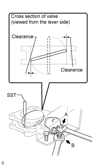
Adjust the exhaust retarder gap (widen the gap).
-
While holding bolt A, loosen nut B.
-
Using SST, turn adjusting bolt A to adjust the valve body clearance.
Standard Clearance 0.2 to 0.3 mm (0.0079 to 0.0118 in.) -
While holding bolt A, tighten nut B.
Torque 5.9 N*m (60 kgf*cm, 52 in.*lbf)
-
NEXT
PERFORM DPF FORCIBLE REGENERATION PROCEDURE
-
REPLACE INJECTOR ASSEMBLY
-
Replace the injector assembly Click here.
NEXT
PERFORM DPF FORCIBLE REGENERATION PROCEDURE
-
-
READ VALUE USING INTELLIGENT TESTER (EXHAUST TEMPERATURE DURING FORCIBLE REGENERATION FUNCTION)
-
Read the exhaust gas temperature during the forcible regeneration function.
Standard Condition Exhaust Temperature B1S2 During forcible regeneration function 220°C (428°F) or more
NG
READ VALUE USING INTELLIGENT TESTER (INJECTION VOLUME DURING FORCIBLE REGENERATION FUNCTION) Click here
OK
REPLACE EXHAUST GAS TEMPERATURE SENSOR (DOWNSTREAM) Click here
-
-
READ VALUE USING INTELLIGENT TESTER (INJECTION VOLUME DURING FORCIBLE REGENERATION FUNCTION)
-
Read the injection volume during the forcible regeneration function.
Standard Condition Injection Volume During forcible regeneration function 18 to 24 mm3/st
NG
ADJUST EXHAUST RETARDER ASSEMBLY Click here
OK
-
-
INSPECT FOR EXHAUST GAS LEAK
-
Check for exhaust gas leak.
NEXT
PERFORM DPF FORCIBLE REGENERATION PROCEDURE
-
-
ADJUST EXHAUST RETARDER ASSEMBLY
- SST
- 09240-00020
-
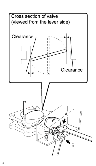
Adjust the exhaust retarder gap (narrow the width of gap).
-
While holding bolt A, loosen nut B.
-
Turn adjusting bolt A to adjust the valve body clearance.
Standard Clearance 0.2 to 0.3 mm (0.0079 to 0.0118 in.) -
While holding bolt A, tighten nut B.
Torque 5.9 N*m (60 kgf*cm, 52 in.*lbf)
-
NEXT
PERFORM DPF FORCIBLE REGENERATION PROCEDURE
-
READ VALUE USING INTELLIGENT TESTER (INJECTION VOLUME DURING FORCIBLE REGENERATION FUNCTION)
-
Read the injection volume during the forcible regeneration function.
Standard Condition Injection Volume During forcible regeneration function 18 to 24 mm3/st
NG
ADJUST EXHAUST RETARDER ASSEMBLY Click here
OK
-
-
READ VALUE USING INTELLIGENT TESTER (FUEL PRESSURE)
-
Stop the forcible regeneration function.
-
Replace the normal DLC3 cable (12 V specification) for the intelligent tester with the 24 V DLC3 cable.
Note
Be sure to use the 24 V DLC3 cable when connecting the intelligent tester to the DLC3. Using the normal DLC3 cable (12 V specification) will cause damage to the tester.
-
Connect the intelligent tester to the DLC3.
-
Start the engine.
-
Turn the tester on.
-
Enter the following menus: Powertrain / Engine and ECT / Data List / Fuel Press.
-
Check that the internal fuel pressure of the common rail is within the specification below.
Standard Engine Speed Fuel Pressure Idling Approximately 25000 to 35000 kPa
NG
REPAIR OR REPLACE FUEL SYSTEM
OK
-
-
INSPECT INJECTION OR SUPPLY PUMP ASSEMBLY
-
Inspect the injection or supply pump assembly Click here.
Result Result Proceed to NG A OK B
B
CLEAN EXHAUST SYSTEM Click here
A
CHECK FUEL INJECTION SYSTEM Click here
-
-
ADJUST EXHAUST RETARDER ASSEMBLY
- SST
- 09240-00020
-
Adjust the exhaust retarder gap (narrow the width of gap).
-
While holding bolt A, loosen nut B.
-
Turn adjusting bolt A to adjust the valve body clearance.
Standard Clearance 0.2 to 0.3 mm (0.0079 to 0.0118 in.) -
While holding bolt A, tighten nut B.
Torque 5.9 N*m (60 kgf*cm, 52 in.*lbf)
-
NEXT
PERFORM DPF FORCIBLE REGENERATION PROCEDURE