ECD SYSTEM DPF Switch and Buzzer Circuit
DESCRIPTION
The DPF (Diesel Particulate Filter) is controlled by the ECM to activate the forcible regeneration function automatically. However, depending on driving conditions, the forcible regeneration function may not be activated. In such a case, the indicator light on the combination meter assembly and the DPF switch light blink to inform the driver. When the DPF switch assembly is pressed with the vehicle stopped, RGSW signals will be input into the ECM and the forcible regeneration function will activate.
If the vehicle continues to be driven without performing forcible regeneration while the indicator light is ON, a buzzer intermittently sounds to inform the driver.
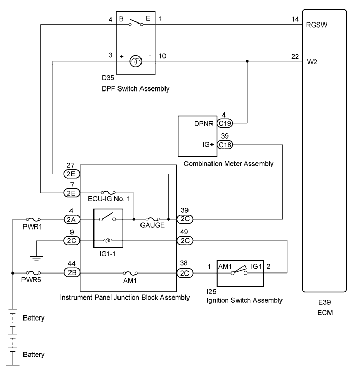
WIRING DIAGRAM
INSPECTION PROCEDURE
Note
Inspect the fuses for circuits related to this system before performing the following inspection procedure.
PROCEDURE
-
CHECK DPF SWITCH ASSEMBLY (POWER SOURCE)
-
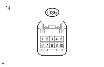
Text in Illustration *a Front view of wire harness connector
(to DPF Switch Assembly)
Disconnect the DPF switch assembly connector.
-
Turn the ignition switch to ON.
-
Measure the voltage according to the value(s) in the table below.
Standard Voltage Tester Connection Switch Condition Specified Condition D35-4 (B) - Body ground Ignition switch ON 18 to 27 V D35-3 (+) - Body ground Ignition switch ON 18 to 27 V -
Turn the ignition switch off.
-
Reconnect the DPF switch assembly connector.
NG 
CHECK HARNESS AND CONNECTOR (DPF SWITCH ASSEMBLY - INSTRUMENT PANEL JUNCTION BLOCK) Click here
OK 
-
-
INSPECT DPF SWITCH ASSEMBLY (RESISTANCE)
-
Inspect the DPF switch assembly Click here.
NG 
REPLACE DPF SWITCH ASSEMBLY Click here
OK
-
-
CHECK HARNESS AND CONNECTOR (DPF SWITCH ASSEMBLY - ECM)
-
Disconnect the DPF switch connector.
-
Disconnect the ECM connectors.
-
Measure the resistance according to the value(s) in the table below.
Standard Resistance (Check for Open) Tester Connection Condition Specified Condition D35-1 (E) - E39-14 (RGSW) Always Below 1 Ω D35-10 (-) - E39-22 (W2) Always Below 1 Ω Standard Resistance (Check for Short) Tester Connection Condition Specified Condition D35-1 (E) or E39-14 (RGSW) - Body ground Always 10 kΩ or higher D35-10 (-) or E39-22 (W2) - Body ground Always 10 kΩ or higher -
Reconnect the DPF switch assembly connector.
-
Reconnect the ECM connectors.
NG
REPAIR OR REPLACE HARNESS OR CONNECTOR (DPF SWITCH ASSEMBLY - ECM)
OK
-
-
CHECK BUZZER OPERATION
-
Replace the normal DLC3 cable (12 V specification) for the intelligent tester with the 24 V DLC3 cable.
Note
Be sure to use the 24 V DLC3 cable when connecting the intelligent tester to the DLC3. Using the normal DLC3 cable (12 V specification) will cause damage to the tester.
-
Connect the intelligent tester to the DLC3.
-
Start the engine.
-
Turn the tester on.
-
Perform the forcible regeneration function Click here.
-
Check that the buzzer sounds during forcible regeneration.
OK The buzzer sounds intermittently.
NG
REPLACE COMBINATION METER ASSEMBLY
OK 
PROCEED TO NEXT SUSPECTED AREA SHOWN IN PROBLEM SYMPTOMS TABLE Click here
-
-
CHECK HARNESS AND CONNECTOR (DPF SWITCH ASSEMBLY - INSTRUMENT PANEL JUNCTION BLOCK)
-
Disconnect the DPF switch assembly connector.
-
Disconnect the instrument panel junction block assembly.
-
Measure the resistance according to the value(s) in the table below.
Standard Resistance (Check for Open) Tester Connection Condition Specified Condition D35-4 (B) - 2E-7 Always Below 1 Ω D35-3 (+) - 2E-27 Always Below 1 Ω 2C-9 - Body ground Always Below 1 Ω Standard Resistance (Check for Short) Tester Connection Condition Specified Condition D35-4 (B) or 2E-7 - Body ground Always 10 kΩ or higher D35-3 (+) or 2E-27 - Body ground Always 10 kΩ or higher -
Reconnect the DPF switch assembly connector.
-
Reconnect the instrument panel junction block assembly.
NG
REPAIR OR REPLACE HARNESS OR CONNECTOR (DPF SWITCH ASSEMBLY - INSTRUMENT PANEL JUNCTION BLOCK)
OK
-
-
INSPECT INSTRUMENT PANEL JUNCTION BLOCK ASSEMBLY (IG1-1 RELAY)
-
Inspect the instrument panel junction block assembly (IG1-1 relay) Click here.
NG
REPLACE INSTRUMENT PANEL JUNCTION BLOCK ASSEMBLY
OK
REPAIR OR REPLACE HARNESS OR CONNECTOR (INSTRUMENT PANEL JUNCTION BLOCK - BATTERY)
-