ECD SYSTEM EDU Power Source Circuit
DESCRIPTION
An injector driver assembly operates the injector assemblies at high speeds. The injector driver assembly allows high-speed driving under high fuel pressure conditions through the use of a voltage converter that provides a high-voltage, quick-charging system. The ECM constantly monitors the injector driver assembly and stops the engine or cuts off fuel supply to some cylinders if an abnormal condition is detected.
WIRING DIAGRAM
Refer to DTC P0201 Click here.
INSPECTION PROCEDURE
Note
Inspect the fuses for circuits related to this system before performing the following inspection procedure.
PROCEDURE
-
CHECK INJECTOR DRIVER ASSEMBLY (POWER SOURCE)
-
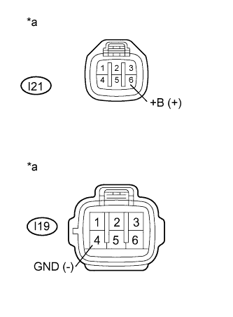
Text in Illustration *a Front view of wire harness connector
(to Injector Driver Assembly)
Disconnect the injector driver assembly connectors.
-
Turn the ignition switch to ON.
-
Measure the voltage according to the value(s) in the table below.
Standard Voltage Tester Connection Switch Condition Specified Condition I21-6 (+B) - I19-4 (GND) Ignition switch ON 18 to 27 V -
Reconnect the injector driver assembly connectors.
NG 
INSPECT EDU RELAY Click here
OK 
CHECK FOR INTERMITTENT PROBLEMS Click here
-
-
INSPECT EDU RELAY
-
Inspect the EDU relay Click here.
NG 
REPLACE EDU RELAY
OK 
-
-
CHECK HARNESS AND CONNECTOR (EDU RELAY - BATTERY)
-
Remove the EDU relay from the engine room relay block and junction block.
-
Disconnect the cable from the negative (-) battery terminal.
-
Disconnect the cable from the positive (+) battery terminal.
-
Measure the resistance according to the value(s) in the table below.
Standard Resistance (Check for Open) Tester Connection Condition Specified Condition EDU relay terminal 3 - Positive (+) battery terminal Always Below 1 Ω Standard Resistance (Check for Short) Tester Connection Condition Specified Condition EDU relay terminal 3 or Positive (+) battery terminal - Body ground Always 10 kΩ or higher -
Reinstall the EDU relay.
-
Reconnect the cable to the positive (+) battery terminal.
-
Reconnect the cable to the negative (-) battery terminal.
NG
REPAIR OR REPLACE HARNESS OR CONNECTOR (EDU RELAY - BATTERY)
OK
-
-
CHECK HARNESS AND CONNECTOR (EDU RELAY - INSTRUMENT PANEL JUNCTION BLOCK)
-
Remove the EDU relay from the engine room relay block and junction block.
-
Disconnect the instrument panel junction block assembly.
-
Measure the resistance according to the value(s) in the table below.
Standard Resistance (Check for Open) Tester Connection Condition Specified Condition EDU relay terminal 1 - 2B-40 Always Below 1 Ω Standard Resistance (Check for Short) Tester Connection Condition Specified Condition EDU relay terminal 1 or 2B-40 - Body ground Always 10 kΩ or higher -
Reinstall the EDU relay.
-
Reconnect the instrument panel junction block assembly.
NG
REPAIR OR REPLACE HARNESS OR CONNECTOR (EDU RELAY - INSTRUMENT PANEL JUNCTION BLOCK)
OK
-
-
CHECK HARNESS AND CONNECTOR (EDU RELAY - ECM)
-
Remove the EDU relay from the engine room relay block and junction block.
-
Disconnect the ECM connector.
-
Measure the resistance according to the value(s) in the table below.
Standard Resistance (Check for Open) Tester Connection Condition Specified Condition EDU relay terminal 2 - E36-20 (IREL) Always Below 1 Ω Standard Resistance (Check for Short) Tester Connection Condition Specified Condition EDU relay terminal 2 or E36-20 (IREL) - Body ground Always 10 kΩ or higher -
Reconnect the ECM connector.
-
Reinstall the EDU relay.
NG
REPAIR OR REPLACE HARNESS OR CONNECTOR (EDU RELAY - ECM)
OK
-
-
CHECK HARNESS AND CONNECTOR (EDU RELAY - INJECTOR DRIVER ASSEMBLY)
-
Disconnect the EDU relay from the engine room relay block and junction block.
-
Disconnect the injector driver assembly connector.
-
Measure the resistance according to the value(s) in the table below.
Standard Resistance (Check for Open) Tester Connection Condition Specified Condition EDU relay terminal 5 - I21-6 (+B) Always Below 1 Ω Standard Resistance (Check for Short) Tester Connection Condition Specified Condition EDU relay terminal 5 or I21-6 (+B) - Body ground Always 10 kΩ or higher -
Reconnect the injector driver assembly connector.
-
Reinstall the EDU relay.
NG
REPAIR OR REPLACE HARNESS OR CONNECTOR (EDU RELAY - INJECTOR DRIVER ASSEMBLY)
OK
-
-
CHECK HARNESS AND CONNECTOR (INJECTOR DRIVER ASSEMBLY - BODY GROUND)
-
Disconnect the injector driver assembly connector.
-
Measure the resistance according to the value(s) in the table below.
Standard Resistance Tester Connection Condition Specified Condition I19-4 (GND) - Body ground Always Below 1 Ω -
Reconnect the injector driver assembly connector.
NG
REPAIR OR REPLACE HARNESS OR CONNECTOR (INJECTOR DRIVER ASSEMBLY - BODY GROUND)
OK
-
-
CHECK ECM (IREL VOLTAGE)
-
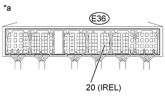
Text in Illustration *a Component with harness connected
(ECM)
Turn the ignition switch to ON.
-
Measure the voltage according to the value(s) in the table below.
Standard Voltage Tester Connection Switch Condition Specified Condition E36-20 (IREL) - Body ground Ignition switch ON 0 to 2 V
NG
CHECK ECM POWER SOURCE CIRCUIT Click here
OK
REPLACE ECM Click here
-