ECD SYSTEM ECM Power Source Circuit
DESCRIPTION
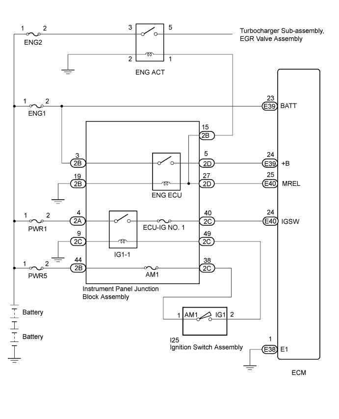
When the ignition switch is turned to ON, battery voltage is applied to terminal IGSW of the ECM. The ECM MREL output signal causes a current to flow to the coil, closing the contacts of the ENG ECU relay and supplying power to terminal +B of the ECM.
WIRING DIAGRAM
INSPECTION PROCEDURE
Note
Inspect the fuses for circuits related to this system before performing the following inspection procedure.
PROCEDURE
-
CHECK ECM (+B VOLTAGE)
-
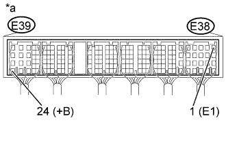
Text in Illustration *a Component with harness connected
(ECM)
Turn the ignition switch to ON.
-
Measure the voltage according to the value(s) in the table below.
Standard Voltage Tester Connection Switch Condition Specified Condition E39-24 (+B) - E38-1 (E1) Ignition switch ON 18 to 27 V
NG 
CHECK HARNESS AND CONNECTOR (ECM - BODY GROUND) Click here
OK 
-
-
INSPECT ENG ACT RELAY
-
Check whether there is a turbocharger sub-assembly or EGR valve assembly power supply malfunction.
OK DTCs related to the turbocharger sub-assembly and EGR valve assembly systems are not output.
NG
INSPECT ENG ACT RELAY Click here
OK 
PROCEED TO NEXT SUSPECTED AREA SHOWN IN PROBLEM SYMPTOMS TABLE Click here
-
-
CHECK HARNESS AND CONNECTOR (ECM - BODY GROUND)
-
Disconnect ECM connector.
-
Measure the resistance according to the value(s) in the table below.
Standard Resistance Tester Connection Condition Specified Condition E38-1 (E1) - Body ground Always Below 1 Ω -
Reconnect the ECM connector.
NG 
REPAIR OR REPLACE HARNESS OR CONNECTOR (ECM - BODY GROUND)
OK
-
-
CHECK ECM (IGSW VOLTAGE)
-
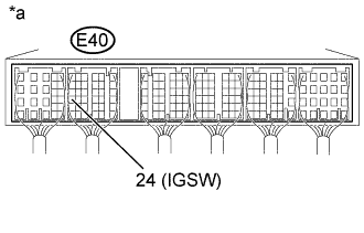
Text in Illustration *a Component with harness connected
(ECM)
Turn the ignition switch to ON.
-
Measure the voltage according to the value(s) in the table below.
Standard Voltage Tester Connection Switch Condition Specified Condition E40-24 (IGSW) - Body ground Ignition switch ON 18 to 27 V
NG
INSPECT INSTRUMENT PANEL JUNCTION BLOCK ASSEMBLY (IG1-1 RELAY) Click here
OK
-
-
CHECK ECM (MREL VOLTAGE)
-
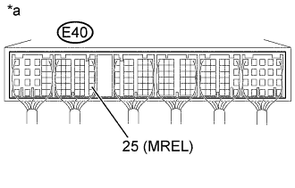
Text in Illustration *a Component with harness connected
(ECM)
Turn the ignition switch to ON.
-
Measure the voltage according to the value(s) in the table below.
Standard Voltage Tester Connection Condition Specified Condition E40-25 (MREL) - Body ground Ignition switch ON 18 to 27 V
NG
INSPECT ENG ACT RELAY Click here
OK
-
-
INSPECT INSTRUMENT PANEL JUNCTION BLOCK ASSEMBLY (ENG ECU RELAY)
-
Inspect the instrument panel junction block assembly (ENG ECU relay) Click here.
NG
REPLACE INSTRUMENT PANEL JUNCTION BLOCK ASSEMBLY (ENG ECU RELAY)
OK
-
-
PERFORM ACTIVE TEST USING HARNESS AND CONNECTOR (INSTRUMENT PANEL JUNCTION BLOCK - ECM)
-
Disconnect the instrument panel junction block assembly.
-
Disconnect the ECM connector.
-
Measure the resistance according to the value(s) in the table below.
Standard Resistance (Check for Open) Tester Connection Condition Specified Condition 2D-5 - E39-24 (+B) Always Below 1 Ω Standard Resistance (Check for Short) Tester Connection Condition Specified Condition 2D-5 or E39-24 (+B) - Body ground Always 10 kΩ or higher -
Reconnect the instrument panel junction block assembly.
-
Reconnect the ECM connector.
NG
REPAIR OR REPLACE HARNESS OR CONNECTOR (INSTRUMENT PANEL JUNCTION BLOCK - ECM)
OK
-
-
CHECK HARNESS AND CONNECTOR (INSTRUMENT PANEL JUNCTION BLOCK - BODY GROUND)
-
Disconnect the instrument panel junction block assembly.
-
Measure the resistance according to the value(s) in the table below.
Standard Resistance Tester Connection Condition Specified Condition 2B-19 - Body ground Always Below 1 Ω -
Reconnect the instrument panel junction block assembly.
NG
REPAIR OR REPLACE HARNESS OR CONNECTOR (INSTRUMENT PANEL JUNCTION BLOCK - BODY GROUND)
OK
-
-
CHECK HARNESS AND CONNECTOR (ECM - INSTRUMENT PANEL JUNCTION BLOCK)
-
Disconnect the instrument panel junction block assembly.
-
Disconnect the ECM connector.
-
Measure the resistance according to the value(s) in the table below.
Standard Resistance (Check for Open) Tester Connection Condition Specified Condition E40-25 (MREL) - 2D-27 Always Below 1 Ω Standard Resistance (Check for Short) Tester Connection Condition Specified Condition E40-25 (MREL) or 2D-27 - Body ground Always 10 kΩ or higher -
Reconnect the instrument panel junction block assembly.
-
Reconnect the ECM connector.
NG
REPAIR OR REPLACE HARNESS OR CONNECTOR (INSTRUMENT PANEL JUNCTION BLOCK - ECM)
OK
REPAIR OR REPLACE HARNESS OR CONNECTOR (INSTRUMENT PANEL JUNCTION BLOCK - BATTERY)
-
-
INSPECT INSTRUMENT PANEL JUNCTION BLOCK ASSEMBLY (IG1-1 RELAY)
-
Inspect the instrument panel junction block assembly (IG1-1 relay) Click here.
NG
REPLACE ENG-2 RELAY (IG1-1 RELAY)
OK
-
-
CHECK HARNESS AND CONNECTOR (INSTRUMENT PANEL JUNCTION BLOCK - ECM)
-
Disconnect the instrument panel junction block assembly.
-
Disconnect the ECM connector.
-
Measure the resistance according to the value(s) in the table below.
Standard Resistance (Check for Open) Tester Connection Condition Specified Condition 2C-40 - E40-24 (IGSW) Always Below 1 Ω Standard Resistance (Check for Short) Tester Connection Condition Specified Condition 2C-40 or E40-24 (IGSW) - Body ground Always 10 kΩ or higher -
Reconnect the instrument panel junction block assembly.
-
Reconnect the ECM connector.
NG
REPAIR OR REPLACE HARNESS OR CONNECTOR (INSTRUMENT PANEL JUNCTION BLOCK - ECM)
OK
-
-
CHECK HARNESS AND CONNECTOR (INSTRUMENT PANEL JUNCTION BLOCK - BODY GROUND)
-
Disconnect the instrument panel junction block assembly.
-
Measure the resistance according to the value(s) in the table below.
Standard Resistance Tester Connection Condition Specified Condition 2C-9 - Body ground Always Below 1 Ω -
Reconnect the instrument panel junction block assembly.
NG
REPAIR OR REPLACE HARNESS OR CONNECTOR (INSTRUMENT PANEL JUNCTION BLOCK - BODY GROUND)
OK
-
-
INSPECT IGNITION SWITCH ASSEMBLY
-
Inspect the ignition switch assembly Click here.
NG
REPLACE IGNITION SWITCH ASSEMBLY
OK
-
-
CHECK HARNESS AND CONNECTOR (IG1-1 RELAY - IGNITION SWITCH ASSEMBLY)
-
Disconnect the instrument panel junction block assembly.
-
Disconnect the ignition switch assembly connector.
-
Measure the resistance according to the value(s) in the table below.
Standard Resistance Check for Open Tester Connection Condition Specified Condition 2C-49 - I25-2 (IG2) Always Below 1 Ω 2C-38 - I25-1 (AM2) Always Below 1 Ω Check for Short Tester Connection Condition Specified Condition 2C-49 or I25-2 (IG2) - Body ground Always 10 kΩ or higher 2C-38 or I25-1 (AM2) - Body ground Always 10 kΩ or higher -
Reconnect the instrument panel junction block assembly.
-
Reconnect the ignition switch assembly connector.
NG
REPAIR OR REPLACE HARNESS OR CONNECTOR (INSTRUMENT PANEL JUNCTION BLOCK - IGNITION SWITCH ASSEMBLY)
OK
REPAIR OR REPLACE HARNESS OR CONNECTOR (INSTRUMENT PANEL JUNCTION BLOCK - BATTERY)
-
-
INSPECT ENG ACT RELAY
-
Inspect the ENG ACT relay Click here.
Tech Tips
If an overcurrent occurs in the MREL output of the ECM due to a short to ground or other malfunction, an element inside the ECM stops the output.
NG
REPLACE ENG ACT RELAY
OK
-
-
CHECK HARNESS AND CONNECTOR (MREL OUTPUT CIRCUIT - BODY GROUND)
Tech Tips
If an overcurrent occurs in the MREL output of the ECM due to a short to ground or other malfunction, an element inside the ECM stops the output.
-
Disconnect the instrument panel junction block assembly.
-
Disconnect the ECM connector.
-
Remove the ENG ACT relay from the engine room relay block and junction block.
-
Measure the resistance according to the value(s) in the table below.
Standard Resistance (Check for Short) Tester Connection Condition Specified Condition 2D-27 or E40-25 (MREL) - Body ground Always 10 kΩ or higher 2B-15 or ENG ACT relay terminal 1 - Body ground Always 10 kΩ or higher -
Reconnect the instrument panel junction block assembly.
-
Reconnect the ECM connector.
-
Reinstall the ENG ACT relay.
NG
REPAIR OR REPLACE HARNESS OR CONNECTOR
OK
REPLACE ECM Click here
-
-
INSPECT ENG ACT RELAY
-
Inspect the ENG ACT relay Click here.
NG
REPLACE ENG ACT RELAY
OK
-
-
CHECK HARNESS AND CONNECTOR (ENG ACT RELAY - INSTRUMENT PANEL JUNCTION BLOCK)
-
Disconnect the instrument panel junction block assembly.
-
Remove the ENG ACT relay from the engine room relay block and junction block.
-
Measure the resistance according to the value(s) in the table below.
Standard Resistance Check for Open Tester Connection Condition Specified Condition 2B-15 - ENG ACT relay terminal 1 Always Below 1 Ω ENG ACT relay terminal 2 - Body ground Always Below 1 Ω Check for Short Tester Connection Condition Specified Condition 2B-15 or ENG ACT relay terminal 1 - Body ground Always 10 kΩ or higher -
Reconnect the instrument panel junction block assembly.
-
Reinstall the ENG ACT relay.
NG
REPAIR OR REPLACE HARNESS OR CONNECTOR
OK
REPAIR OR REPLACE HARNESS OR CONNECTOR (ENG ACT RELAY - BATTERY)
-