ENGINE ASSEMBLY REMOVAL

-
REMOVE ENGINE UNDER COVER
-
DISCONNECT CABLE FROM NEGATIVE BATTERY TERMINAL
-
DRAIN ENGINE OIL
-
Remove the oil filler cap sub-assembly.
-
Remove the drain plug from the oil pan and drain engine oil into a container.
-
Clean the drain plug.
-
Install the drain plug with a new gasket.
- Torque:
- 41 N*m { 418 kgf*cm, 30 ft.*lbf }
-
-
DRAIN ENGINE COOLANT
CAUTION:
Do not remove the radiator cap sub-assembly while the engine and radiator are still hot. Pressurized, hot engine coolant and steam may be released and cause serious burns.
-
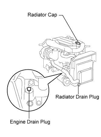
Loosen the radiator drain cock plug and engine drain plug.
-
Remove the radiator cap, then drain the coolant.
-
Close the radiator drain cock plug.
-
Tighten the engine drain plug.
- Torque:
- 27 N*m { 275 kgf*cm, 20 ft.*lbf, for the engine drain plug }
-
-
DRAIN POWER STEERING FLUID
-
REMOVE ENGINE SIDE COVER SUB-ASSEMBLY LH
-
REMOVE ENGINE SIDE COVER SUB-ASSEMBLY RH
-
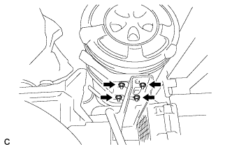
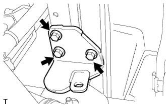
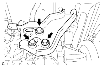
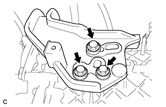
REMOVE RADIATOR RESERVE TANK ASSEMBLY
-
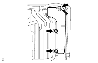
Remove the bolt and 3 nuts.
-
Remove the radiator reserve tank assembly.
-
-
REMOVE FENDER SIDE APRON SUB-ASSEMBLY LH
-
REMOVE FENDER SIDE APRON SUB-ASSEMBLY RH
-
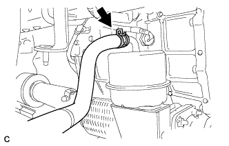
REMOVE VACUUM RESERVOIR SUB-ASSEMBLY
-
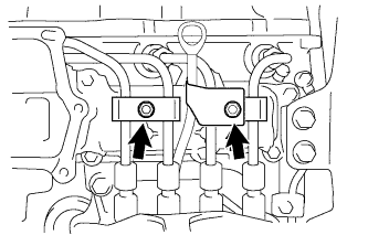
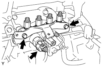
REMOVE SPILL VALVE CONTROL DRIVER ASSEMBLY
-
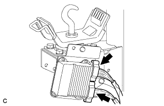
Disconnect the 2 injector driver connectors.
-
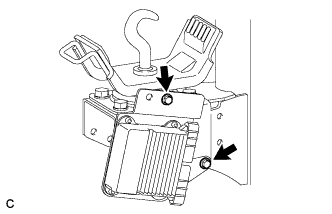
Remove the 2 bolts and remove the injector driver.
-
-
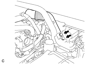
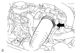
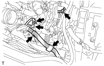
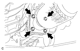
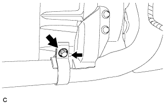
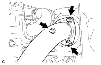
REMOVE NO. 2 INTAKE PIPE
-
Remove the 3 bolts, loosen the 2 bands, and remove the No. 2 intake pipe.
-
-
REMOVE NO. 3 CAB MOUNTING BRACKET SUB-ASSEMBLY
-

Disconnect the connector. (with Cab tilt warning)
-
Remove the 4 nuts and remove the air cleaner case.
-
Remove the 2 bolts and remove the No. 1 air hose assembly.
-
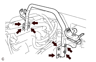
Remove the 8 bolts and remove the No. 3 cab mounting bracket.
-
-
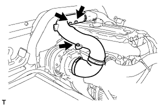
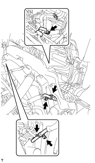
REMOVE NO. 1 INTAKE AIR PIPE WITH NO. 4 AIR HOSE
-
Disconnect the hose band.
-
Remove the 2 bolts and bracket.
-
Disconnect the turbo pressure sensor connector and wire harness clamp, and remove the bolt.
-
Disconnect the intake air temperature sensor connector, and remove the bolt.
-
Disconnect the hose band, and remove the No. 1 intake air pipe with No. 4 air hose.
-
-
REMOVE NO. 2 AIR HOSE
-
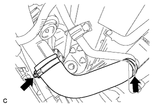
Disconnect the 2 hose bands and No. 1 air hose.
-
-
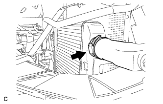
REMOVE INTERCOOLER ASSEMBLY
-
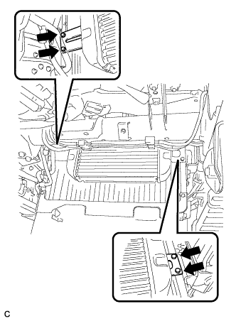
Remove the 4 bolts and intercooler assembly.
-
-
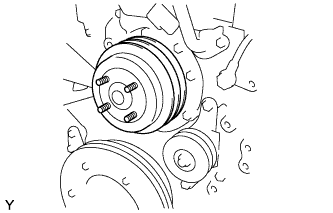
REMOVE FAN
-
Remove the 4 nuts.
-
Remove the fan and generator V belt.
Tech Tips
-
Remove the 4 nuts and remove the pulley and fan.
-
-
REMOVE FAN PULLEY
-
Remove the fan pulley.
-
-
DISCONNECT RADIATOR HOSE INLET
-
Disconnect the radiator hose inlet.
-
-
DISCONNECT RADIATOR HOSE OUTLET
-
Remove the radiator hose outlet.
-
-
SEPARATE HEATER HOSE
-
Remove the 5 bolts and separate the heater hose.
-
-
SEPARATE NO. 4 RADIATOR BRACKET
-

Remove the 3 bolts and separate the No. 4 radiator bracket.
-
Remove the bolt and radiator support No. 2.
-
-
SEPARATE NO. 3 RADIATOR BRACKET
-
Remove the 3 bolts and separate the No. 3 radiator bracket.
-
Remove the bolt and No. 1 radiator support.
-
-
REMOVE RADIATOR ASSEMBLY
-
Remove the radiator assembly with fan shroud.
-
-
REMOVE GENERATOR ASSEMBLY
-
Remove the terminal cap and the nut, disconnect the wire harness from terminal B.
-
Disconnect the connector from the generator.
-
Disconnect the 3 wire harness clamps.
-

Remove the 4 bolts, generator bracket and generator assembly.
-
-
REMOVE STARTER ASSEMBLY
-

Disconnect the 2 wire harness clamps.
-
Remove the bolt and the wire harness clamp bracket.
-
Pull off the terminal cap and remove the bolt, and disconnect the starter wire from terminal B.
-
Pull off the terminal cap and remove the nut, and disconnect the starter wire from terminal C.
-
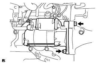
Remove the nut, bolt and the starter assembly.
-
-
DISCONNECT HEATER HOSE
-
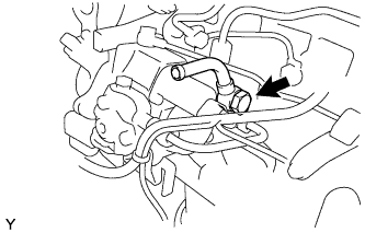
REMOVE EXHAUST RETARDER ASSEMBLY
-
Disconnect the vacuum hose.
-
Remove the 4 bolts and exhaust retarder assembly.
-
Remove the 2 gaskets.
-
-
REMOVE FRONT EXHAUST PIPE ASSEMBLY
-
Remove the bolt.
-
Remove the 3 nuts and front exhaust pipe assembly.
-
Remove the gasket.
-
-
DISCONNECT PROPELLER SHAFT ASSEMBLY
-
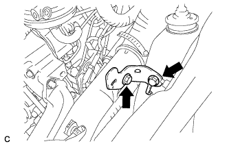
SEPARATE CLUTCH RELEASE CYLINDER ASSEMBLY
-
Remove the 2 bolts and disconnect the clutch release cylinder.
-
-
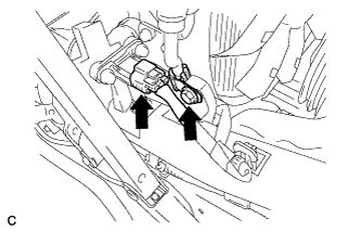
DISCONNECT FLOOR SHIFT CABLE TRANSMISSION CONTROL SELECT
-
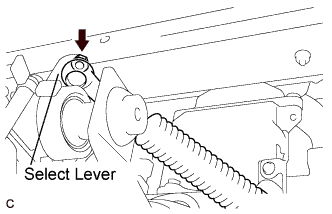
Remove the nut and control select cable from the select lever.
-
-
DISCONNECT FLOOR SHIFT CABLE TRANSMISSION CONTROL SHIFT
-
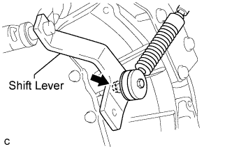
Remove the nut and control shift cable from the shift lever.
-
-
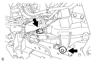
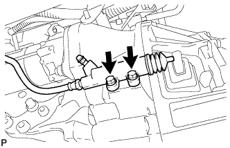
DISCONNECT NO. 2 OIL RESERVOIR TO PUMP HOSE
-
Disconnect the No. 2 oil reservoir to pump hose.
-
-
REMOVE PRESSURE FEED HOSE
-
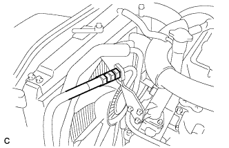
Using SST, separate the pressure feed hose.
- SST
- 09023-12901
-
Remove the gasket from the pressure feed hose.
-
-
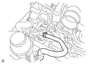
DISCONNECT FUEL HOSE
-
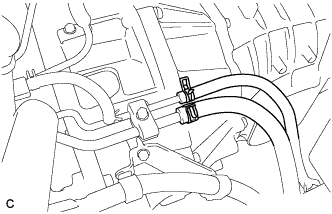
Disconnect the 2 fuel hoses.
-
-
DISCONNECT WIRE HARNESS
-
Disconnect the wire harness.
-
-
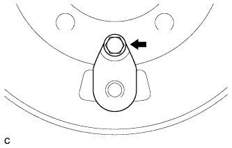
REMOVE MANUAL TRANSMISSION OUTPUT SHAFT REAR SET NUT
-
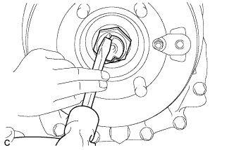
Using a chisel and a hammer, release the staked part of the transmission output shaft rear set nut.
-
Pull the parking brake lever fully, and shift into the reverse position.
-
Using a 36 mm socket wrench, remove the transmission output shaft rear set nut.
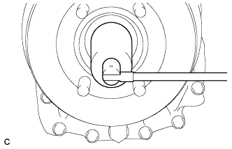
-
Using a screwdriver, remove the O-ring.
-
-
REMOVE PARKING BRAKE DRUM SUB-ASSEMBLY
-
Remove the bolt and dust cover from the parking brake drum.
-
Release the parking brake lever.
-
Remove the parking brake drum sub-assembly and companion flange.
-
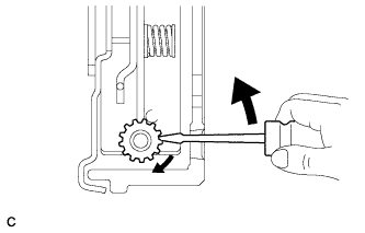
If the brake drum cannot be removed easily, turn the shoe adjuster in the direction of the illustrated arrow mark until the drum turns freely.
-
-
SEPARATE PARKING BRAKE PLATE SUB-ASSEMBLY
-
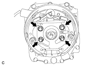
Remove the 4 nuts and disconnect the parking brake plate sub-assembly.
Tech Tips
Use wire or an equivalent tool to keep the parking brake plate sub-assembly from hanging down by the parking brake cable.
-
-
SUPPORT TRANSMISSION ASSEMBLY
-
Support the transmission assembly with a transmission jack.
-
-
DISCONNECT NO. 3 ENGINE MOUNTING BRACKET
-
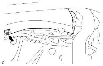
Remove the nut.
-
Remove the 3 bolts and 3 washers and disconnect the No. 3 engine mounting bracket.
-
-
DISCONNECT NO. 1 ENGINE MOUNTING BRACKET
-
Remove the nut.
-
Remove the 3 bolts and 3 washers and disconnect the No. 1 engine mounting bracket.
-
-
SUPPORT ENGINE ASSEMBLY
-

Install the engine hanger with the 2 bolts.
- Torque:
- 108 N*m { 1100 kgf*cm, 80 ft.*lbf }
-

Attach the sling device and the engine with the chain block.
-
-
REMOVE MANUAL TRANSMISSION ASSEMBLY
-
Disconnect the connector and clamp.
-
Remove the 12 bolts.
-
Remove the transmission assembly.
Note
Do not apply excessive force to the transmission assembly as this will cause the input shaft to break.
-
-
REMOVE CLUTCH COVER ASSEMBLY
-
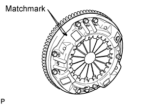
Put matchmarks on the clutch cover assembly and the flywheel sub-assembly.
-
Loosen each set bolt one turn at a time until spring tension is released.
-
Remove the set bolts, and pull off the clutch cover assembly.
Note
Do not drop the clutch disc assembly.
-
-
REMOVE CLUTCH DISC ASSEMBLY
Note
Keep the lining part of the clutch disc assembly, the pressure plate and the surface of the flywheel sub-assembly away from oil and foreign matter.
-
REMOVE ENGINE ASSEMBLY
-
Remove the 2 nuts and engine from the engine mounting brackets.
-
Remove the engine hanger.
-
-
REMOVE EGR COOLER SUB-ASSEMBLY
-
Separate the water by-pass hose.
-
Remove the 6 bolts and remove the EGR cooler.
-
-
REMOVE OIL FILLER CAP SUB-ASSEMBLY
-

Remove the oil filler cap sub-assembly.
-
-
REMOVE NO. 2 CYLINDER HEAD COVER SUB-ASSEMBLY
-
Remove the 2 bolts and remove the No. 2 cylinder head cover sub-assembly.
-
-
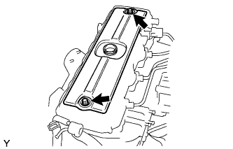
REMOVE CYLINDER HEAD COVER SUB-ASSEMBLY
-

Remove the wire harness.
-
Remove the cylinder head cover cushion rubber.
-
Remove the 2 bolts and remove the cylinder head cover sub-assembly.
-
-
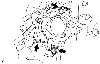
REMOVE DIESEL THROTTLE BODY
-
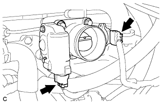
Disconnect the 2 diesel throttle body connectors.
-
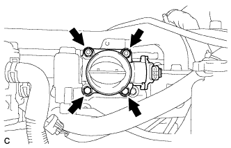
Remove the 2 bolts, 2 nuts and diesel throttle body.
-
-
SEPARATE WIRE HARNESS AND CONNECTORS
-
Disconnect the 3 connectors.
-
-
REMOVE VENTILATION PIPE SUB-ASSEMBLY
-
Remove the 2 bolts.
-
Disconnect the 3 hoses and remove the ventilation pipe sub-assembly.
-
-
REMOVE EGR VALVE BRACKET
-
Remove the 4 bolts and bracket.
-
-
REMOVE OIL SEPARATOR ASSEMBLY
-
Move the clamp and disconnect the hose.
-
Remove the 2 bolts and the oil separator assembly.
-
-
REMOVE WATER BY-PASS PIPE SUB-ASSEMBLY
-
Remove the 3 bolts and 2 union bolts.
-
Remove the water by-pass pipe.
-
-
REMOVE VENTURI ASSEMBLY
-
Remove the 4 bolts, 2 nuts and venturi from the intake manifold.
-
-
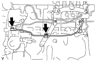
REMOVE INJECTION PIPE CLAMP
-
Remove the 2 nuts, oil level dipstick guide and the 2 pipe clamps.
-
-
REMOVE OIL LEVEL GAUGE GUIDE
-
Remove the oil level gauge guide.
-
-
REMOVE INJECTOR ASSEMBLY
-
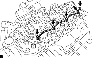
Remove the union bolt, the 4 hollow screws, the 5 gaskets and the nozzle leakage pipe.
Note
After removing the nozzle leakage pipe, put it in a plastic bag to prevent foreign matter from contaminating its injector.
-
Using a small screwdriver, move the 4 holder seals.
-

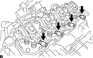
Remove the 4 bolts and the 4 nozzle holder clamps.
Note
Arrange the holder clamps and bolts in the correct order.
-
Remove the 4 injectors.
Note
Arrange the injectors in the correct order.
-
Remove the No. 2 cylinder head cover gasket from each injector.
-
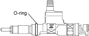
Remove the O-ring from each injector.
-
Remove the 4 injection nozzle seats from the cylinder head.
-
-
REMOVE VANE PUMP ASSEMBLY
-
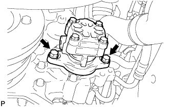
Remove the 2 bolts and remove the vane pump assembly.
-
Remove the vane pump O-ring from the vane pump assembly.
-
-
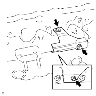
REMOVE GENERATOR BELT ADJUSTING BAR
-
Remove the 2 bolts and remove the generator belt adjusting bar.
-
-
REMOVE GENERATOR BRACKET SUB-ASSEMBLY
-
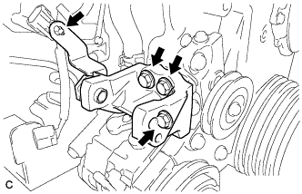
Remove the 3 bolts and remove the generator bracket.
-
-
REMOVE RADIATOR PIPE
-
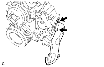
Remove the 2 bolts and remove the radiator pipe.
-
-
REMOVE TURBOCHARGER SUB-ASSEMBLY
Tech Tips
-
REMOVE EXHAUST MANIFOLD
-
Remove the 3 bolts and remove the exhaust manifold heat insulator sub-assembly.
-
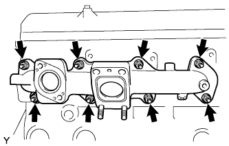
Remove the 8 nuts and remove the exhaust manifold.
-
-
REMOVE ENGINE OIL PRESSURE SWITCH ASSEMBLY
-
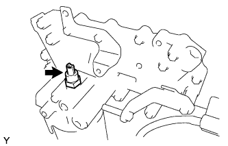
Remove the engine oil pressure switch assembly.
-
-
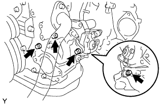
REMOVE OIL COOLER ASSEMBLY
-
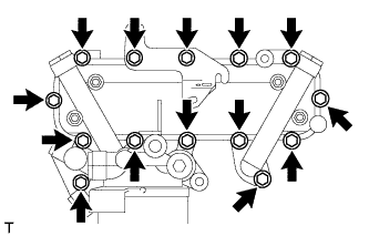
Remove the 15 bolts and oil cooler assembly with bracket.
-

Remove the 4 nuts and oil cooler assembly.
-
Remove the 2 gaskets.
-
-
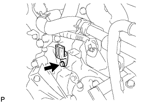
REMOVE CRANKSHAFT POSITION SENSOR
-
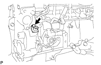
Remove the bolt and remove the crankshaft position sensor.
-
-
REMOVE CAMSHAFT POSITION SENSOR
-
Remove the bolt and remove the camshaft position sensor.
-
-
REMOVE WATER OUTLET SUB-ASSEMBLY
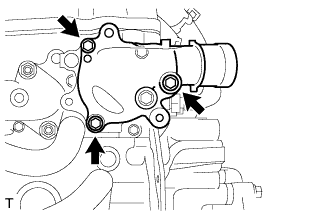
Remove the 3 bolts and remove the water outlet sub-assembly.
-
REMOVE THERMOSTAT
-
Remove the 3 bolts and water outlet.
-
Remove the thermostat from the cylinder block.
-
Remove the gasket from the thermostat.
-
-
REMOVE WATER TEMPERATURE SENDER GAUGE ASSEMBLY
-
Disconnect the connector.
-
Remove the water temperature sender gauge assembly.
-
-
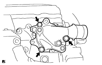
REMOVE WATER OUTLET HOUSING
-

Remove the 3 bolts and remove the water outlet housing.
-
-
REMOVE WATER PIPE SUB-ASSEMBLY
-
Remove the 3 bolts and remove the water pipe sub-assembly.
-
-
REMOVE WATER BY-PASS PIPE SUB-ASSEMBLY
-
Remove the 7 bolts and remove the water by-pass pipe sub-assembly.
-
-
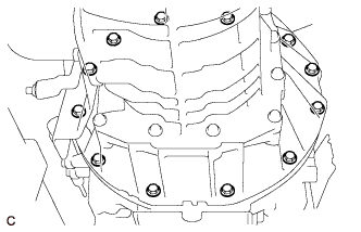
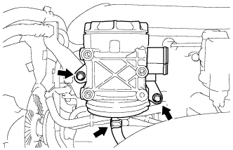
REMOVE WATER PUMP ASSEMBLY
-

Remove the 8 bolts and water pump assembly.
-
-
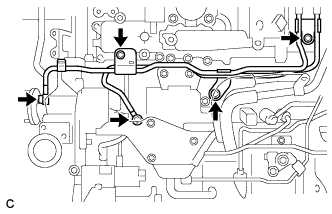
REMOVE VACUUM PIPE
-
Remove the union bolt and bolt and remove the vacuum pipe.
-
-
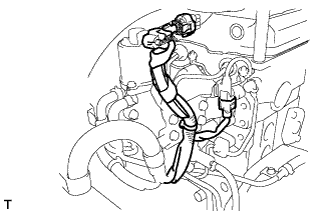
REMOVE VACUUM PUMP OIL PIPE SUB-ASSEMBLY
-
Remove the 3 bolts and remove the vacuum pump oil pipe sub-assembly.
-
-
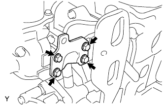
REMOVE VACUUM PUMP ASSEMBLY
-

Remove the 2 nuts and remove the vacuum pump assembly.
-
-
REMOVE NO. 4 FUEL PIPE SUB-ASSEMBLY
-
Remove the 2 union bolts, the 4 gaskets and the No. 4 fuel pipe sub-assembly.
-
-
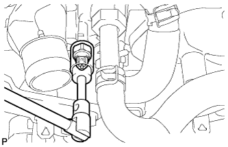
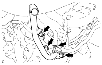
REMOVE FUEL FILTER TO INJECTION PUMP FUEL PIPE
-
Remove the nut and the fuel pipe clamp.
-
Using SST, loosen the union nuts and remove the fuel filter to injection pump fuel pipe.
- SST
- 09023-12901
-
-
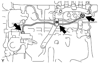
REMOVE COMMON RAIL ASSEMBLY
-
Disconnect the fuel pressure sensor connector.
-
Remove the 2 bolts, the No. 3 injection pipe bracket and the common rail assembly.
-
-
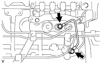
REMOVE FUEL DELIVERY PIPE
-
Remove the union bolt, the 2 gaskets and the fuel delivery pipe.
-
-
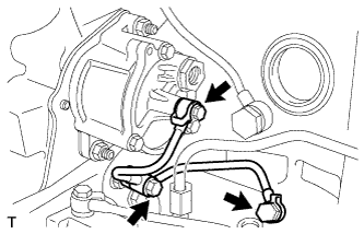
REMOVE FUEL RETURN PIPE SUB-ASSEMBLY
-
Remove the nut and the fuel pipe clamp.
-
Remove the union bolt, the gasket and the fuel return pipe sub-assembly.
-
-
REMOVE INJECTION OR SUPPLY PUMP ASSEMBLY
-
Disconnect the 2 connectors.
-
Remove the bolt and the holder clip.
-
Remove the 4 bolts and the injection or supply pump assembly.
-
Remove the O-ring from the timer cover.
-
-
REMOVE INTAKE MANIFOLD
-

Remove the 8 bolts and 2 nuts and remove the intake manifold.
-