CYLINDER BLOCK REASSEMBLY

-
INSTALL CAMSHAFT BEARING
-
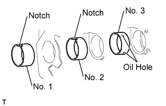
Be sure to face the notches of the No. 1 and No. 2 camshaft bearings and the oil holes of the No. 3 camshaft bearing in the correct direction.
-
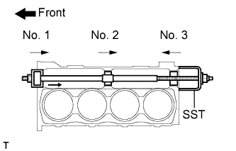
Using SST, install new camshaft bearings in the direction indicated by the arrow marks in the illustration.
- SST
- 09215-00101 ( 09215-00130, 09215-00141, 09215-00150, 09215-00161 )
- 09215-00013 ( 09215-00021, 09215-00461 )
Journal bearing diameter Journal No. Inside diameter Outside diameter No. 1 57.0 mm (2.2441 in.) 60.0 mm (2.3622 in.) No. 2 56.8 mm (2.2362 in.) 59.8 mm (2.3543 in.) No. 3 56.6 mm (2.2283 in.) 59.6 mm (2.3465 in.) Note
Install the No. 2, No. 1 and No. 3 camshaft bearings in order.
-
-
INSTALL CONNECTING ROD SMALL END BUSH
-
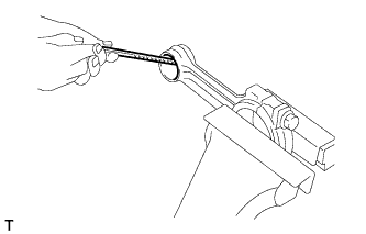
Uniformly chamfer one edge of the bush hole at the small end of the connecting rod.
Tech Tips
-
Incorrect chamfering can cause the bush to run out-of-round, which may result in jamming during insertion.
-
Remove dust from the inner surface of the connecting rod hole.
-
-
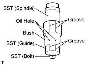
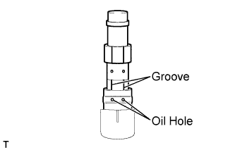
Mount the bush on the spindle.
- SST
- S0940-21470
- S0948-11140
- S9191-08252
- Torque:
- 6.0 N*m { 61 kgf*cm, 53 in.*lbf }
Tech Tips
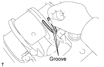
Align the oil holes in the bush with both grooves of the spindle and guide, and make sure that oil holes will meet with the oil path in the connecting rod led from the big end bore in the rod.
-
Apply fresh engine oil around the bush and guide.
-
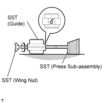
Prepare SST.
- SST
- S0940-21450
- S0948-11130
- S9233-10360
-
Assemble the guide and press sub-assembly by inserting its pin into the guide, then secure them with the wing nut.
Tech Tips
Orient the letter W, stamped on the guide, above the pin.
-
Make sure to align both supporting surfaces of the guide and press sub-assembly on an even plane.
-
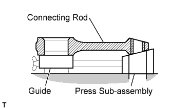
Install the bush into the connecting rod. Position the spindle and bush so that the oil holes align with the oil path through the connecting rod.
Tech Tips
Before installing, fully coat the bore in the connecting rod with fresh engine oil.
-
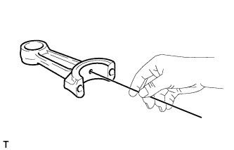
Inspect the bush position after installation.
-
Make sure that the oil hole of the bush and the oil path of the connecting rod are suitably aligned, allowing a 6 mm (0.23 in.) diameter rod to penetrate.
Tech Tips
Misalignment can lead to insufficient lubrication, which may result in piston seizure.
-
With a new piston pin inserted in the piston, make sure that the pin can be rotated by hand without looseness.
-
-
-
INSTALL PISTON PIN HOLE SNAP RING
-
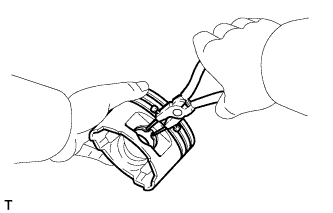
Using snap ring pliers, install a new snap ring on one side of the piston hole.
-
-
INSTALL PISTON
Tech Tips
Before assembling the piston with the connecting rod, check whether the piston is specified for this engine.
Check should be performed using the engine compatible identification code on the top of the piston.
Engine compatible identification code 95
-
Assemble the piston and connecting rod.
-
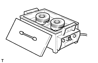
Gradually heat the piston to approximately 50°C (122°F).
CAUTION:
Never touch the piston by hand while it is hot.
-
Coat the piston pin with engine oil.
-
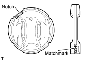
Install the piston to the connecting rod with the notch of the piston facing in the same direction as the matchmark of the rod. Then, insert the piston pin.
-
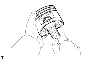
Check that the piston and piston pin fit securely.
Tech Tips
Try to move the piston back and forth.
-
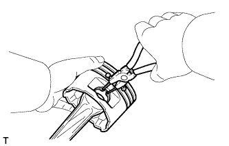
Using snap ring pliers, install a new snap ring on the other side of the piston pin hole.
-
-
-
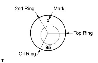
INSTALL PISTON RING SET
-
Face the identification marks on the piston ring up, then using a piston ring expander, install them in the following order: the oil ring, 2nd ring and 1st ring.
Tech Tips
-
Never change the combination of the coil and oil ring.
-
Connect the joint of the coil expander for the oil ring and install it inside the oil ring. Align the expander joint 180° opposite to the gap of the ring.
-
-
-
INSTALL NO. 1 OIL NOZZLE SUB-ASSEMBLY
-
Install the No. 1 oil nozzle with the bolt.
- Torque:
- 29 N*m { 290 kgf*cm, 21 ft.*lbf }
Note
-
If an oil nozzle has been dropped impacted, replace the nozzle with a new one.
-
Replace any deformed nozzle with a new one.
-
-
INSTALL CRANKSHAFT BEARING SET
-
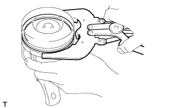
Align the oil groove of the bearing with the oil hole of the cylinder block, and push in the 5 upper bearings.
Note
Keep the back side of the bearing and the bearing surface free of foreign matter.
-
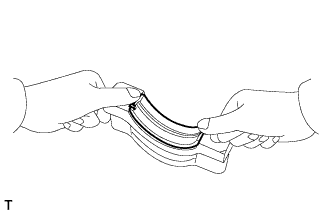
Align the bearing with the crankshaft bearing cap, and push in the 5 lower bearings.
Note
Keep the back side of the bearing and the bearing surface free of foreign matter.
-
Install the crankshaft.
-
Insert the thrust washer into the clearance between the cylinder block and crankshaft with the oil groove facing outward.
-
Install the main bearing cap to the cylinder block.
-
Apply a light coat of engine oil to the threads and under the cap bolt.
Note
Be sure to install the removed thrust washer to its original position.
-
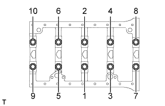
Temporarily tighten the bolts in several steps, in the sequence shown in the illustration.
-
Tighten the bolts to the specified torque.
- Torque:
- 60 N*m { 610 kgf*cm, 44 ft.*lbf }
-
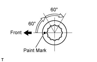
Mark the front of the bearing cap bolts with paint.
-
Retighten the bolts by 60° and then an additional 60° as shown in the illustration.
-
-
INSTALL CYLINDER LINER
Tech Tips
-
When assembling the cylinder liner in the cylinder block, clearance can be set to 3 levels.
-
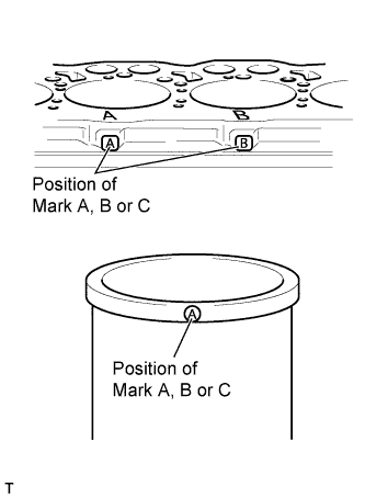
The upper surface and side surface of the cylinder block are stamped A, B or C. When using a new cylinder liner, insert a matching cylinder liner having the same symbol.
-
Apply engine oil to the cylinder block inside bore.
-
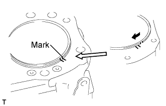
Align the marks of the cylinder liner and cylinder block.
Tech Tips
When reusing the cylinder liner, install it according to the marks made during the removal. When reusing the cylinder liner, misalignment with the cylinder block may concentrate stress on the thin part of the cylinder liner and the cylinder liner may break.
-
Install the cylinder liner.
Note
Make sure to install the cylinder liner to its original location.
-
-
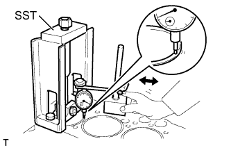
INSPECT PROTRUSION OF CYLINDER LINER
-
Install SST onto the cylinder block.
- SST
- S0942-01460
-
Tighten the center bolt to the specified torque below to set the SST in the proper installation position.
- Torque:
- 9.8 N*m { 100 kgf*cm, 7.2 ft.*lbf }
-
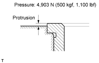
Using a dial indicator, measure the protrusion of the cylinder liner.
Standard protrusion 0.01 to 0.08 mm (0.0004 to 0.0031 in.) Maximum protrusion 0.08 mm (0.0031 in.) If the protrusion is greater than the maximum, replace the cylinder liner.
-
-
INSTALL CONNECTING ROD BEARING
Note
-
When reusing the bearing, make sure to reassemble the removed bearing as it was originally installed.
-
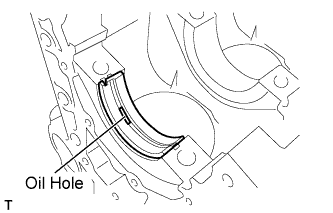
Install the bearing with the oil hole on the connecting rod side and install the bearing without the oil hole on the cap side.
-
Match the bearing protrusion with the notch of the connecting rod or cap.
-
Keep the back side of the bearing and bearing surface of the bearing cap free of foreign matter.
-
-
INSTALL PISTON SUB-ASSEMBLY WITH CONNECTING ROD
Tech Tips
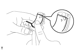
Position the piston ring end gaps an even distance apart from each other as shown in the illustration. Do not align the ring end gaps.
-
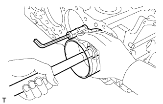
Using a piston ring compressor and a hammer handle, insert the piston with connecting rod assembly into the cylinder block.
Tech Tips
-
Before installation, apply engine oil to the piston pin, piston ring, cylinder liner and connecting rod bearing.
-
Recheck the gap of each piston ring.
-
Do not damage the inside of the liner.
-
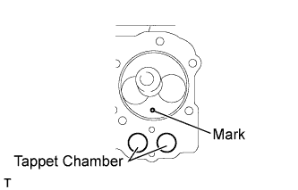
Make sure that the mark on the piston is at the tappet chamber side.
-
-
Install the bearing cap to the connecting rod with the front mark facing in the correct direction.
-
Uniformly install and tighten the bolts to the specified torque in several steps.
- Torque:
- 30 N*m { 300 kgf*cm, 22 ft.*lbf }
-
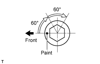
Mark the front side of the bolt head with paint as shown in the illustration.
-
Retighten the bolts by 60°.
-
Perform step (e) again.
-
Check that each painted mark is now at a 120° angle to the front.
-