ECD SYSTEM, Diagnostic DTC:P1133

| DTC Code | DTC Name |
|---|---|
| P1133 | Power Take-off Accel Position Sensor Circuit High |
DESCRIPTION
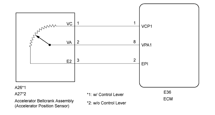
The external accelerator position sensor is installed on the accelerator bellcrank assembly and is used to control the power take-off system. The sensor converts the position of the power take-off accelerator into a linear signal of approximately 0 to 5 V and sends the signal to the ECM.
| DTC Detection Drive Pattern | DTC Detection Condition | Trouble Area |
|---|---|---|
| - | The output of the power take-off accelerator position sensor is 4.8 V or higher for 1 second or more while the engine is running. (1 trip detection logic) |
|
WIRING DIAGRAM
INSPECTION PROCEDURE
Note
After replacing the ECM, the new ECM needs registration Click here and initialization Click here.
PROCEDURE
-
READ VALUE USING INTELLIGENT TESTER (ACCEL SENSOR VOLTAGE)
-
Replace the normal DLC3 cable (12 V specification) for the intelligent tester with the 24 V DLC3 cable.
Note
Be sure to use the 24 V DLC3 cable when connecting the intelligent tester to the DLC3. Using the normal DLC3 cable (12 V specification) will cause damage to the tester.
-
Connect the intelligent tester to the DLC3.
-
Turn the ignition switch to ON.
-
Turn the tester on.
-
Enter the following menus: Powertrain / Engine and ECT / Data List / Accel Sensor Voltage.
-
Read the value displayed on the tester when the accelerator bellcrank assembly is fully open and fully closed.
Result Accelerator Bellcrank Assembly State Reference Fully closed 0.6 to 1.0 V fully open 3.3 to 3.7 V
NG 
CHECK ECM (VCP1 AND VPA1 VOLTAGE) Click here
OK 
CHECK FOR INTERMITTENT PROBLEMS Click here
-
-
CHECK ECM (VCP1 AND VPA1 VOLTAGE)
-
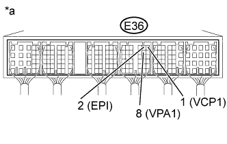
Text in Illustration *a Component with harness connected
(ECM)
Turn the ignition switch to ON.
-
Measure the voltage according to the value(s) in the table below.
Standard Voltage Tester Connection Switch Condition Specified Condition E36-1 (VCP1) - E36-2 (EP1) Ignition switch ON 4.5 to 5.5 V E36-8 (VPA1) - E36-2 (EP1) Accelerator bellcrank assembly fully closed 0.7 to 1.0 V Accelerator bellcrank assembly fully open 3.3 to 3.9 V Accelerator bellcrank assembly fully closed → fully open Voltage changes without interruption
NG
INSPECT ACCELERATOR BELLCRANK ASSEMBLY Click here
OK
REPLACE ECM Click here
-
-
INSPECT ACCELERATOR BELLCRANK ASSEMBLY
-
Disconnect the accelerator bellcrank assembly connector.
-
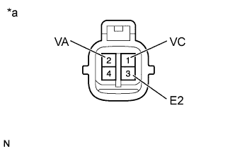
Text in Illustration *a Component without harness connected
(Accelerator Bellcrank Assembly)
Measure the resistance according to the value(s) in the table below.
Standard Resistance Tester Connection Condition Specified Condition 1 (VC) - 3 (E2) - 1.6 to 2.4 kΩ 2 (VA) - 3 (E2) Accelerator fully closed → fully open Value changes without interruption
NG 
REPLACE ACCELERATOR BELLCRANK ASSEMBLY
OK 
-
-
CHECK HARNESS AND CONNECTOR
-
Disconnect the accelerator bellcrank assembly connector.
-
Disconnect the ECM connector.
-
Measure the resistance according to the value(s) in the table below.
Standard Resistance (Check for Open) Tester Connection Condition Specified Condition A26*1-1 (VC) - E36-1 (VCP1) Always Below 1 Ω A26*1-2 (VA) - E36-8 (VAP1) Always Below 1 Ω A26*1-3 (E2) - E36-2 (EP1) Always Below 1 Ω A27*2-1 (VC) - E36-1 (VCP1) Always Below 1 Ω A27*2-2 (VA) - E36-8 (VAP1) Always Below 1 Ω A27*2-3 (E2) - E36-2 (EP1) Always Below 1 Ω *1: w/ Control Lever
*2: w/o Control Lever
Standard Resistance (Check for Short) Tester Connection Condition Specified Condition A26*1-1 (VC) or E36-1 (VCP1) - Body ground Always 10 kΩ or higher A26*1-2 (VA) or E36-8 (VAP1) - Body ground Always 10 kΩ or higher A26*1-3 (E2) or E36-2 (EP1) - Body ground Always 10 kΩ or higher A27*2-1 (VC) or E36-1 (VCP1) - Body ground Always 10 kΩ or higher A27*2-2 (VA) or E36-8 (VAP1) - Body ground Always 10 kΩ or higher A27*2-3 (E2) or E36-2 (EP1) - Body ground Always 10 kΩ or higher *1: w/ Control Lever
*2: w/o Control Lever
-
Reconnect the accelerator bellcrank assembly connector.
-
Reconnect the ECM connector.
NG
REPAIR OR REPLACE HARNESS AND CONNECTOR
OK
REPLACE ECM Click here
-