ECD SYSTEM, Diagnostic DTC:P0201, P0202, P0203, P0204, P062D

| DTC Code | DTC Name |
|---|---|
| P0201 | Injector Circuit / Open - (Cylinder 1) |
| P0202 | Injector Circuit / Open - (Cylinder 2) |
| P0203 | Injector Circuit / Open - (Cylinder 3) |
| P0204 | Injector Circuit / Open - (Cylinder 4) |
| P062D | No. 1 Fuel Injector Driver Circuit Performance |
DESCRIPTION
The injector driver assembly operates the injector assembly at high speeds. The injector driver assembly allows high-speed driving under high fuel pressure conditions through the use of a voltage converter that provides a high-voltage, quick-charging system.
The ECM constantly monitors the injector driver assembly and stops the engine if an abnormal condition is detected.
| DTC Detection Drive Pattern | DTC Detection Condition | Trouble Area |
|---|---|---|
| Idling for 5 seconds | Open or short in No. 1 injector circuit occurs a certain number of times (1 trip detection logic) |
|
| DTC Detection Drive Pattern | DTC Detection Condition | Trouble Area |
|---|---|---|
| Idling for 5 seconds | Open or short in No. 2 injector circuit occurs a certain number of times (1 trip detection logic) |
|
| DTC Detection Drive Pattern | DTC Detection Condition | Trouble Area |
|---|---|---|
| Idling for 5 seconds | Open or short in No. 3 injector circuit occurs a certain number of times (1 trip detection logic) |
|
| DTC Detection Drive Pattern | DTC Detection Condition | Trouble Area |
|---|---|---|
| Idling for 5 seconds | Open or short in No. 4 injector circuit occurs a certain number of times (1 trip detection logic) |
|
| DTC Detection Drive Pattern | DTC Detection Condition | Trouble Area |
|---|---|---|
| Idling for 5 seconds | Inconsistency in the injection waveforms between the injector driver and ECM while the engine is running a certain number of times (1 trip detection logic) |
|
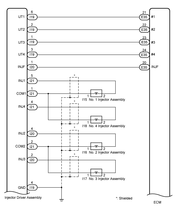
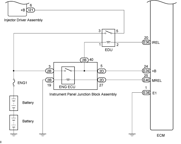
WIRING DIAGRAM
INSPECTION PROCEDURE
Note
-
After replacing the ECM, the new ECM needs registration Click here and initialization Click here.
-
After replacing the injector assembly, the ECM needs registration Click here.
Tech Tips
Read freeze frame data using the intelligent tester. The ECM records vehicle and driving condition information as freeze frame data the moment a DTC is stored. When troubleshooting, freeze frame data can be helpful in determining whether the vehicle was moving or stationary, whether the engine was warmed up or not, as well as other data recorded at the time of a malfunction.
PROCEDURE
-
CHECK INJECTOR DRIVER ASSEMBLY (+B VOLTAGE)
-
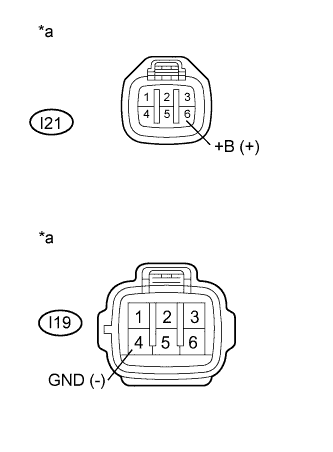
Text in Illustration *a Front view of wire harness connector
(to Injector Driver Assembly)
Disconnect the injector driver assembly connectors.
-
Turn the ignition switch to ON.
-
Measure the voltage according to the value(s) in the table below.
Standard Voltage Tester Connection Switch Condition Specified Condition I21-6 (+B) - I19-4 (GND) Ignition switch ON 18 to 27 V -
Reconnect the injector driver assembly connectors.
NG 
CHECK EDU POWER SOURCE CIRCUIT Click here
OK 
-
-
CHECK INJECTOR DRIVER ASSEMBLY (INJECTOR ASSEMBLY RESISTANCE)
-
Disconnect the injector driver assembly connector.
-
Measure the resistance according to the value(s) in the table below.
Standard Resistance Tester Connection Condition Specified Condition I21-5 (INJ1) - I21-1 (COM1) 20°C (68°F) 0.37 to 0.57 Ω I20-4 (INJ2) - I21-2 (COM2) 20°C (68°F) 0.37 to 0.57 Ω I20-2 (INJ3) - I21-2 (COM2) 20°C (68°F) 0.37 to 0.57 Ω I21-4 (INJ4) - I21-1 (COM1) 20°C (68°F) 0.37 to 0.57 Ω -
Reconnect the injector driver assembly connector.
NG 
INSPECT INJECTOR ASSEMBLY Click here
OK
-
-
CHECK HARNESS AND CONNECTOR (INJECTOR DRIVER ASSEMBLY - ECM)
-
Disconnect the injector driver assembly connector.
-
Disconnect the ECM connector.
-
Measure the resistance according to the value(s) in the table below.
Standard Resistance (Check for Open) Tester Connection Condition Specified Condition I19-6 (IJT1) - E35-21 (#1) Always Below 1 Ω I19-2 (IJT2) - E35-22 (#2) Always Below 1 Ω I19-1 (IJT3) - E35-23 (#3) Always Below 1 Ω I19-3 (IJT4) - E35-24 (#4) Always Below 1 Ω I20-1 (INJF) - E35-20 (INJF) Always Below 1 Ω Standard Resistance (Check for Short) Tester Connection Condition Specified Condition I19-6 (IJT1) or E35-21 (#1) - Body ground Always 10 kΩ or higher I19-2 (IJT2) or E35-22 (#2) - Body ground Always 10 kΩ or higher I19-1 (IJT3) or E35-23 (#3) - Body ground Always 10 kΩ or higher I19-3 (IJT4) or E35-24 (#4) - Body ground Always 10 kΩ or higher I20-1 (INJF) or E35-20 (INJF) - Body ground Always 10 kΩ or higher -
Reconnect the injector driver assembly connector.
-
Reconnect the ECM connector.
NG
REPAIR OR REPLACE HARNESS OR CONNECTOR (INJECTOR DRIVER ASSEMBLY - ECM)
OK
-
-
CHECK ECM (OUTPUT VOLTAGE)
-
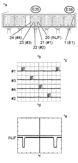
Text in Illustration *a Component with harness connected
(ECM)
*b Signal Waveform *c 5 V/DIV. *d 20 ms./DIV. *e 2 V/DIV. *f 1 ms./DIV. While idling the engine, check the waveform of the ECM connectors using an oscilloscope.
Standard Tester Connection Specified Condition E35-21 (#1) - E38-1 (E1) Correct waveform appears as shown E35-22 (#2) - E38-1 (E1) Correct waveform appears as shown E35-23 (#3) - E38-1 (E1) Correct waveform appears as shown E35-24 (#4) - E38-1 (E1) Correct waveform appears as shown E35-20 (INJF) - E38-1 (E1) Correct waveform appears as shown Result Result Proceed to #1 to #4 is normal, INJF is abnormal A #1 to #4 is abnormal, INJF is normal B
B
REPLACE ECM Click here
A 
REPLACE INJECTOR DRIVER ASSEMBLY Click here
-
-
INSPECT INJECTOR ASSEMBLY
-
Inspect the injector assembly Click here.
NG
REPLACE INJECTOR ASSEMBLY Click here
OK
REPAIR OR REPLACE HARNESS OR CONNECTOR (INJECTOR DRIVER ASSEMBLY - INJECTOR ASSEMBLY)
-