ECD SYSTEM, Diagnostic DTC:P0102, P0103

| DTC Code | DTC Name |
|---|---|
| P0102 | Mass or Volume Air Flow Circuit Low Input |
| P0103 | Mass or Volume Air Flow Circuit High Input |
DESCRIPTION
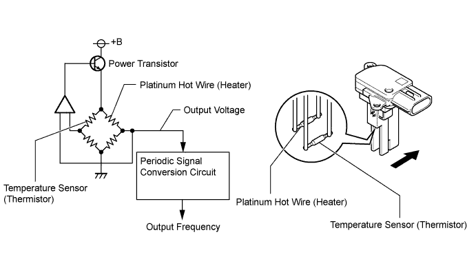
The intake mass air flow meter assembly consists of a platinum hot wire, temperature sensor and control circuit installed in a plastic housing. The temperature sensor (located in the intake air by-pass of the housing) detects the intake air temperature.
There is little variation in the output from the intake mass air flow meter assembly, as it is hardly affected by the resistance of the wire harness.
The internal circuit of the intake mass air flow meter assembly contains a hot wire and cold wire. A voltage is output through a bridge circuit (refer to the illustration) indicating the cooling of the hot wire according to the intake air amount. This voltage is then converted into a periodic signal by the periodic signal conversion circuit and output to the ECM. The frequency varies between approximately 1945 and 8500 Hz depending on the air flow rate. The ECM calculates the mass air flow rate based on this frequency.
| DTC Detection Drive Pattern | DTC Detection Condition | Trouble Area |
|---|---|---|
| 3 seconds after engine is started | Mass air flow meter signal frequency is less than 850 Hz with the engine speed at 5000 rpm or less for 3 seconds (1 trip detection logic). |
|
| DTC Detection Drive Pattern | DTC Detection Condition | Trouble Area |
|---|---|---|
| 3 seconds after engine is started | Mass air flow meter signal frequency is more than 9800 Hz with the engine speed at 5000 rpm or less for 3 seconds (1 trip detection logic). |
|
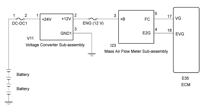
WIRING DIAGRAM
INSPECTION PROCEDURE
Note
-
After replacing the ECM, the new ECM needs registration Click here and initialization Click here.
-
Inspect the fuses for circuits related to this system before performing the following inspection procedure.
Tech Tips
Read freeze frame data using the intelligent tester. The ECM records vehicle and driving condition information as freeze frame data the moment a DTC is stored. When troubleshooting, freeze frame data can be helpful in determining whether the vehicle was moving or stationary, whether the engine was warmed up or not, as well as other data recorded at the time of a malfunction.
PROCEDURE
-
CHECK MASS AIR FLOW METER SUB-ASSEMBLY (POWER SOURCE)
-
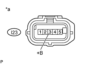
Text in Illustration *a Front view of wire harness connector
(to Mass Air Flow Meter Sub-assembly)
Disconnect the mass air flow meter sub-assembly connector.
-
Turn the ignition switch to ON.
-
Measure the voltage according to the value(s) in the table below.
Standard Voltage Tester Connection Switch Condition Specified Condition I23-3 (+B) - Body ground Ignition switch ON 11 to 14 V -
Reconnect the mass air flow meter sub-assembly connector.
NG 
CHECK HARNESS AND CONNECTOR (MASS AIR FLOW METER SUB-ASSEMBLY - VOLTAGE CONVERTER SUB-ASSEMBLY) Click here
OK 
-
-
CHECK HARNESS AND CONNECTOR (MASS AIR FLOW METER SUB-ASSEMBLY - ECM)
-
Disconnect the mass air flow meter sub-assembly connector.
-
Disconnect the ECM connector.
-
Measure the resistance according to the value(s) in the table below.
Standard Resistance (Check for Open) Tester Connection Condition Specified Condition I23-5 (FC) - E35-17 (VG) Always Below 1 Ω I23-4 (E2G) - E35-18 (EVG) Always Below 1 Ω Standard Resistance (Check for Short) Tester Connection Condition Specified Condition I23-5 (FC) or E35-17 (VG) - Body ground Always 10 kΩ or higher -
Reconnect the mass air flow meter sub-assembly connector.
-
Reconnect the ECM connector.
NG 
REPAIR OR REPLACE HARNESS OR CONNECTOR (MASS AIR FLOW METER SUB-ASSEMBLY - ECM)
OK
-
-
REPLACE MASS AIR FLOW METER SUB-ASSEMBLY
-
Replace the mass air flow meter sub-assembly Click here.
NEXT
-
-
CHECK DTC OUTPUT
-
Replace the normal DLC3 cable (12 V specification) for the intelligent tester with the 24 V DLC3 cable.
Note
Be sure to use the 24 V DLC3 cable when connecting the intelligent tester to the DLC3. Using the normal DLC3 cable (12 V specification) will cause damage to the tester.
-
Connect the intelligent tester to the DLC3.
-
Turn the ignition switch to ON.
-
Turn the tester on.
-
Enter the following menus: Powertrain / Engine and ECT / DTC.
-
Read the DTCs.
Result Result Proceed to P0102 or P0103 is output A DTC is not output B
B
END
A 
REPLACE ECM Click here
-
-
CHECK HARNESS AND CONNECTOR (MASS AIR FLOW METER SUB-ASSEMBLY - VOLTAGE CONVERTER SUB-ASSEMBLY)
-
Disconnect the mass air flow meter sub-assembly connector.
-
Disconnect the voltage converter connector.
-
Measure the resistance according to the value(s) in the table below.
Standard Resistance (Check for Open) Tester Connection Condition Specified Condition I23-3 (+B) - V11-2 (+12V) Always Below 1 Ω Standard Resistance (Check for Short) Tester Connection Condition Specified Condition I23-3 (+B) or V11-2 (+12V) - Body ground Always 10 kΩ or higher -
Reconnect the mass air flow meter sub-assembly connector.
-
Reconnect the voltage converter connector.
NG
REPAIR OR REPLACE HARNESS OR CONNECTOR (MASS AIR FLOW METER SUB-ASSEMBLY - VOLTAGE CONVERTER SUB-ASSEMBLY)
OK
CHECK VOLTAGE CONVERTER SYSTEM Click here
-