ECD SYSTEM, Diagnostic DTC:P0101

| DTC Code | DTC Name |
|---|---|
| P0101 | Mass Air Flow Circuit Range / Performance Problem |
DESCRIPTION
Refer to DTC P0102 Click here.
| DTC Detection Drive Pattern | DTC Detection Condition | Trouble Area |
|---|---|---|
| After warming up the engine coolant to 70°C (158°F), idle the engine for 10 seconds or more, and then maintain an engine speed of 2000 rpm or higher for 10 seconds or more. | Air flow rate from mass air flow meter sub-assembly is out of specified threshold under the following conditions (2 trip detection logic):
|
|
INSPECTION PROCEDURE
Tech Tips
Read freeze frame data using the intelligent tester. The ECM records vehicle and driving condition information as freeze frame data the moment a DTC is stored. When troubleshooting, freeze frame data can be helpful in determining whether the vehicle was moving or stationary, whether the engine was warmed up or not, as well as other data recorded at the time of a malfunction.
PROCEDURE
-
CHECK OTHER DTC OUTPUT (IN ADDITION TO DTC P0101)
-
Replace the normal DLC3 cable (12 V specification) for the intelligent tester with the 24 V DLC3 cable.
Note
Be sure to use the 24 V DLC3 cable when connecting the intelligent tester to the DLC3. Using the normal DLC3 cable (12 V specification) will cause damage to the tester.
-
Connect the intelligent tester to the DLC3.
-
Turn the ignition switch to ON.
-
Turn the tester on.
-
Enter the following menus: Powertrain / Engine and ECT / DTC.
-
Read the DTCs.
Result Result Proceed to DTC P0101 is output A DTC P0101 and other DTCs are output B
B 
GO TO DTC CHART Click here
A 
-
-
CHECK AIR FILTER
-
Visually check that the air filter is not excessively contaminated with dirt or oil.
NG
CLEAN OR REPLACE AIR FILTER
OK
-
-
INSPECT INTAKE SYSTEM
-
Inspect the intake system Click here.
NG
REPAIR OR REPLACE INTAKE SYSTEM
OK
-
-
CHECK HARNESS AND CONNECTOR (MASS AIR FLOW METER SUB-ASSEMBLY - ECM)
-
Disconnect the mass air flow meter sub-assembly connector.
-
Disconnect the ECM connector.
-
Measure the resistance according to the value(s) in the table below.
Standard Resistance (Check for Open) Tester Connection Condition Specified Condition I23-5 (FC) - E35-17 (VG) Always Below 1 Ω I23-4 (E2G) - E35-18 (EVG) Always Below 1 Ω Standard Resistance (Check for Short) Tester Connection Condition Specified Condition I23-5 (FC) or E35-17 (VG) - Body ground Always 10 kΩ or higher -
Reconnect the mass air flow meter sub-assembly connector.
-
Reconnect the ECM connector.
NG
REPAIR OR REPLACE HARNESS OR CONNECTOR
OK
-
-
CHECK MASS AIR FLOW METER SUB-ASSEMBLY (POWER SOURCE)
-
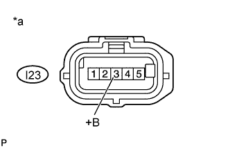
Text in Illustration *a Front view of wire harness connector
(to Mass Air Flow Meter Sub-assembly)
Disconnect the mass air flow meter sub-assembly connector.
-
Turn the ignition switch to ON.
-
Measure the voltage according to the value(s) in the table below.
Standard Voltage Tester Connection Switch Condition Specified Condition I23-3 (+B) - Body ground Ignition switch ON 11 to 14 V -
Reconnect the mass air flow meter sub-assembly connector.
NG
CHECK VOLTAGE CONVERTER SYSTEM Click here
OK
-
-
REPLACE MASS AIR FLOW METER SUB-ASSEMBLY
-
Replace the mass air flow meter sub-assembly Click here.
NEXT
-
-
CHECK WHETHER DTC OUTPUT RECURS
-
Replace the normal DLC3 cable (12 V specification) for the intelligent tester with the 24 V DLC3 cable.
Note
Be sure to use the 24 V DLC3 cable when connecting the intelligent tester to the DLC3. Using the normal DLC3 cable (12 V specification) will cause damage to the tester.
-
Connect the intelligent tester to the DLC3.
-
Clear the DTCs Click here.
-
Turn the ignition switch off for 30 seconds or more.
-
Start the engine
-
Warm up the engine coolant temperature to 70°C (158°F).
-
Maintain engine idle for 10 seconds or more.
-
Maintain an engine speed of 2000 rpm or higher for 10 seconds or more.
-
Turn the tester on.
-
Enter the following menus: Powertrain / Engine and ECT / DTC.
-
Read the DTCs using the intelligent tester.
Result Display (DTC output) Proceed to DTC is not output A DTC P0101 is output B
B
REPLACE ECM
A 
END
-