ECD SYSTEM, Diagnostic DTC:P0087, P0190, P0191, P0192, P0193

| DTC Code | DTC Name |
|---|---|
| P0087 | Fuel Rail / System Pressure - Too Low |
| P0190 | Fuel Rail Pressure Sensor Circuit |
| P0191 | Fuel Rail Pressure Sensor Circuit Range / Performance |
| P0192 | Fuel Rail Pressure Sensor Circuit Low Input |
| P0193 | Fuel Rail Pressure Sensor Circuit High Input |
DESCRIPTION
The fuel pressure sensor, mounted on the common rail assembly, converts the fuel pressure into an electric signal and outputs the signal to the ECM. Based on the signal from the fuel pressure sensor, the ECM controls the injection or supply pump assembly (suction control valve) and keeps the internal fuel pressure of the common rail assembly at the target fuel pressure.
| DTC Detection Drive Pattern | DTC Detection Condition | Trouble Area |
|---|---|---|
| After idling for 60 seconds, quickly increase engine speed to 2500 rpm repeatedly for 30 seconds | Conditions (a), (b) and (c) are met 10 times with engine speed 580 rpm or more: (a) Battery voltage: 16 V or more (b) Fuel quantity: 28 mm3/st or more (c) Amount of change in fuel pressure applied to common rail assembly: 100 kPa or less |
|
| DTC Detection Drive Pattern | DTC Detection Condition | Trouble Area |
|---|---|---|
| Ignition switch ON for 1 second | Fuel pressure sensor output voltage is 0.55 V or less, or 4.9 V or higher for 1 second (1 trip detection logic). |
|
| DTC Detection Drive Pattern | DTC Detection Condition | Trouble Area |
|---|---|---|
| Idling for 1 second | The difference between the main and sub voltage outputs of the fuel pressure sensor is 0.04 V or less, or 1.06 V or higher for 1 second or more (1 trip detection logic). |
|
| DTC Detection Drive Pattern | DTC Detection Condition | Trouble Area |
|---|---|---|
| Ignition switch ON for 1 second | Fuel pressure sensor output voltage is 0.55 V or less for 1 second (1 trip detection logic). |
|
| DTC Detection Drive Pattern | DTC Detection Condition | Trouble Area |
|---|---|---|
| Ignition switch ON for 1 second | Fuel pressure sensor output voltage is 4.9 V or higher for 1 second (1 trip detection logic). |
|
Tech Tips
-
If the vehicle runs out of fuel, and the ECM determines that the fuel pressure has decreased, DTC P0192 may be output.
-
When DTC P0087, P0190, P0191, P0192 and/or P0193 are set, check the internal fuel pressure of the common rail assembly by entering the following menus on the intelligent tester: Powertrain / Engine and ECT / Data List / Fuel Press.
| Fuel Press | Malfunction |
|---|---|
| Approximately 0 kPa (0 kg/cm2, 0 psi) |
|
| Approximately 190000 kPa (1937 kg/cm2, 27556 psi) or more |
|
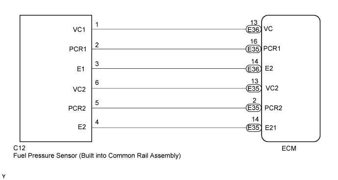
WIRING DIAGRAM
INSPECTION PROCEDURE
Note
After replacing the ECM, the new ECM needs registration Click here and initialization Click here.
Tech Tips
-
Read freeze frame data using the intelligent tester. The ECM records vehicle and driving condition information as freeze frame data the moment a DTC is stored. When troubleshooting, freeze frame data can be helpful in determining whether the vehicle was moving or stationary, whether the engine was warmed up or not, as well as other data recorded at the time of a malfunction.
-
If different DTCs that are related to a different system are output simultaneously while terminal E2 is used as a ground terminal, terminal E2 may be open.
PROCEDURE
-
CHECK DTC OUTPUT
-
Replace the normal DLC3 cable (12 V specification) for the intelligent tester with the 24 V DLC3 cable.
Note
Be sure to use the 24 V DLC3 cable when connecting the intelligent tester to the DLC3. Using the normal DLC3 cable (12 V specification) will cause damage to the tester.
-
Connect the intelligent tester to the DLC3.
-
Turn the ignition switch to ON and turn the tester on.
-
Enter the following menus: Powertrain / Engine and ECT / DTC.
-
Read the DTCs.
Result Result Proceed to P0190, P0191, P0192 or P0193 is output A P0087 is output B
B 
REPLACE COMMON RAIL ASSEMBLY (FUEL PRESSURE SENSOR) Click here
A 
-
-
CHECK HARNESS AND CONNECTOR (ECM - FUEL PRESSURE SENSOR)
-
Disconnect the ECM connector.
-
Disconnect the fuel pressure sensor connector.
-
Measure the resistance according to the value(s) in the table below.
Standard Resistance (Check for Open) Tester Connection Condition Specified Condition E36-13 (VC) - C12-1 (VC1) Always Below 1 Ω E35-16 (PCR1) - C12-2 (PCR1) Always Below 1 Ω E36-14 (E2) - C12-3 (E1) Always Below 1 Ω E35-13 (VC2) - C12-6 (VC2) Always Below 1 Ω E35-2 (PCR2) - C12-5 (PCR2) Always Below 1 Ω E35-14 (E21) - C12-4 (E2) Always Below 1 Ω Standard Resistance (Check for Short) Tester Connection Condition Specified Condition E36-13 (VC) or C12-1 (VC1) - Body ground Always 10 kΩ or higher E35-16 (PCR1) or C12-2 (PCR1) - Body ground Always 10 kΩ or higher E35-13 (VC2) or C12-6 (VC2) - Body ground Always 10 kΩ or higher E35-2 (PCR2) or C12-5 (PCR2) - Body ground Always 10 kΩ or higher -
Reconnect the fuel pressure sensor connector.
-
Reconnect the ECM connector.
NG
REPAIR OR REPLACE HARNESS OR CONNECTOR Click here
OK
-
-
INSPECT ECM (OUTPUT VOLTAGE)
-
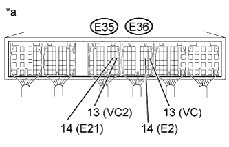
Text in Illustration *a Component with harness connected
(ECM)
Turn the ignition switch to ON.
-
Measure the voltage according to the value(s) in the table below.
Standard Voltage Tester Connection Switch Condition Specified Condition E36-13 (VC) - E36-14 (E2) Ignition switch to ON 4.5 to 5.5 V E35-13 (VC2) - E35-14 (E21) Ignition switch to ON 4.5 to 5.5 V
NG
REPLACE ECM Click here
OK
-
-
REPLACE COMMON RAIL ASSEMBLY (FUEL PRESSURE SENSOR)
-
Replace the common rail assembly Click here.
NEXT
-
-
BLEED AIR FROM FUEL SYSTEM
-
Bleed the air from the fuel system Click here.
NEXT
-
-
CHECK WHETHER DTC OUTPUT RECURS (DTC P0087, P0190, P0191, P0192, P0193)
-
Replace the normal DLC3 cable (12 V specification) for the intelligent tester with the 24 V DLC3 cable.
Note
Be sure to use the 24 V DLC3 cable when connecting the intelligent tester to the DLC3. Using the normal DLC3 cable (12 V specification) will cause damage to the tester.
-
Connect the intelligent tester to the DLC3.
-
Turn the ignition switch to ON and turn the tester on.
-
Clear the DTCs Click here.
-
Let the engine idle for 60 seconds, and then quickly increase the engine speed to 2500 rpm repeatedly for 30 seconds.
-
Enter the following menus: Powertrain / Engine and ECT / DTC.
-
Read the DTCs.
Result Result Proceed to P0087, P0190, P0191, P0192 or P0193 is output A No DTC is output B
B 
END
A
-
-
REPLACE ECM
-
Replace the ECM Click here.
NEXT
CONFIRM WHETHER MALFUNCTION HAS BEEN SUCCESSFULLY REPAIRED Click here
-
-
REPAIR OR REPLACE HARNESS OR CONNECTOR
-
Repair or replace the harness or connector.
NEXT
-
-
CONFIRM WHETHER MALFUNCTION HAS BEEN SUCCESSFULLY REPAIRED
-
Replace the normal DLC3 cable (12 V specification) for the intelligent tester with the 24 V DLC3 cable.
Note
Be sure to use the 24 V DLC3 cable when connecting the intelligent tester to the DLC3. Using the normal DLC3 cable (12 V specification) will cause damage to the tester.
-
Connect the intelligent tester to the DLC3.
-
Clear the DTCs Click here.
-
Turn the ignition switch off for 30 seconds or more.
-
Turn the ignition switch to ON.
-
Let the engine idle for 60 seconds, and then quickly increase the engine speed to 2500 rpm repeatedly for 30 seconds.
-
Confirm that the DTC is not output again.
Tech Tips
Perform the following procedure using the tester to determine whether or not the DTC judgment has been carried out.
-
Enter the following menus: Powertrain / Engine and ECT / Utility / All Readiness.
-
Input DTC P0087, P0190, P0191, P0192 and/or P0193.
-
Check that STATUS is NORMAL. If STATUS is INCOMPLETE or N/A, increase the idling time.
-
NEXT 
END
-