ECD SYSTEM, Diagnostic DTC:P2269

| DTC Code | DTC Name |
|---|---|
| P2269 | Water in Fuel Condition |
DESCRIPTION
-
This DTC is stored when there is water in the fuel filter.
| DTC Detection Drive Pattern | DTC Detection Condition | Trouble Area |
|---|---|---|
| Ignition switch ON for 180 seconds | The water level warning switch remains ON for 3 minutes or more. (1 trip detection logic) |
|
Tech Tips
When water accumulates in the diesel fuel filter assembly, a light in the combination meter assembly comes on, which indicates that the water must be drained from the diesel fuel filter assembly.
When a vehicle is brought in for service, if rust is found on fuel injection-related parts, checking whether DTC P2269 has been stored will help in determining whether the rust occurred due to water in the diesel fuel filter assembly.
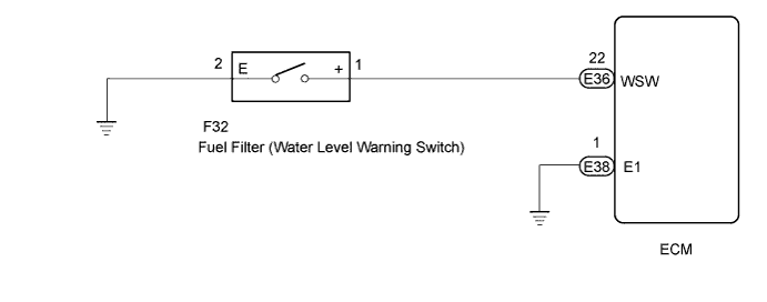
WIRING DIAGRAM
INSPECTION PROCEDURE
Note
After replacing the ECM, the new ECM needs registration Click here and initialization Click here.
Tech Tips
Read freeze frame data using the intelligent tester. The ECM records vehicle and driving condition information as freeze frame data the moment a DTC is stored. When troubleshooting, freeze frame data can be helpful in determining whether the vehicle was moving or stationary, whether the engine was warmed up or not, as well as other data recorded at the time of a malfunction.
PROCEDURE
-
INSPECT DIESEL FUEL FILTER ASSEMBLY
-
Drain the water from the fuel filter assembly.
NEXT 
-
-
CHECK WHETHER DTC OUTPUT RECURS (DTC P2269)
-
Replace the normal DLC3 cable (12 V specification) for the intelligent tester with the 24 V DLC3 cable.
Note
Be sure to use the 24 V DLC3 cable when connecting the intelligent tester to the DLC3. Using the normal DLC3 cable (12 V specification) will cause damage to the tester.
-
Connect the intelligent tester to the DLC3.
-
Turn the ignition switch to ON and turn the tester on.
-
Clear the DTCs Click here.
-
Turn the ignition switch to ON for 180 seconds or more.
-
Enter the following menus: Powertrain / Engine and ECT / DTC.
-
Read the DTCs.
Result Result Proceed to DTC P2269 is output A DTC is not output B
A 
CHECK HARNESS AND CONNECTOR (WATER LEVEL WARNING SWITCH - ECM) Click here
B 
END
-
-
CHECK HARNESS AND CONNECTOR (WATER LEVEL WARNING SWITCH - ECM)
-
Disconnect the water level warning switch connector.
-
Disconnect the ECM connector.
-
Measure the resistance according to the value(s) in the table below.
Standard Resistance (Check for Open) Tester Connection Condition Specified Condition F32-1 (+) - E36-22 (WSW) Always Below 1 Ω Standard Resistance (Check for Short) Tester Connection Condition Specified Condition F32-1 (+) or E36-22 (WSW) - Body ground Always 10 kΩ or higher -
Reconnect the water level warning switch connector.
-
Reconnect the ECM connector.
NG 
REPAIR OR REPLACE HARNESS OR CONNECTOR
OK
-
-
CHECK HARNESS AND CONNECTOR (WATER LEVEL WARNING SWITCH - BODY GROUND)
-
Disconnect the water level warning switch connector.
-
Disconnect the ECM connector.
-
Measure the resistance according to the value(s) in the table below.
Standard Resistance (Check for Open) Tester Connection Condition Specified Condition F32-2 (E) - Body ground Always Below 1 Ω -
Reconnect the water level warning switch connector.
-
Reconnect the ECM connector.
NG
REPAIR OR REPLACE HARNESS OR CONNECTOR
OK
-
-
INSPECT WATER LEVEL WARNING SWITCH
-
Inspect the water level warning switch Click here.
NG
REPLACE WATER LEVEL WARNING SWITCH Click here
OK
REPLACE ECM Click here
-