ECD SYSTEM Starter Signal Circuit
DESCRIPTION
When the engine is being cranked, the intake air flow is slow, so fuel vaporization is poor. A rich mixture is therefore necessary in order to achieve good startability. While the engine is being cranked, the battery positive voltage is applied to terminal STA of the ECM. The starter signal is mainly used to increase the fuel injection volume for starting injection control and after-start injection control.
WIRING DIAGRAM
Refer to DTC P0617 Click here.
INSPECTION PROCEDURE
Note
Inspect the fuses for circuits related to this system before performing the following inspection procedure.
PROCEDURE
-
READ VALUE USING INTELLIGENT TESTER
-
Replace the normal DLC3 cable (12 V specification) for the intelligent tester with the 24 V DLC3 cable.
Note
Be sure to use the 24 V DLC3 cable when connecting the intelligent tester to the DLC3. Using the normal DLC3 cable (12 V specification) will cause damage to the tester.
-
Connect the intelligent tester to the DLC3.
-
Turn the ignition switch to ON.
-
Turn the tester on.
-
Enter the following menus: Powertrain / Engine and ECT / Data List / Starter Signal.
-
Read the value.
OK Ignition Switch Condition ON START Starter Signal OFF ON
NG 
CHECK STARTER RELAY ASSEMBLY (POWER SOURCE) Click here
OK 
PROCEED TO NEXT SUSPECTED AREA SHOWN IN PROBLEM SYMPTOMS TABLE Click here
-
-
CHECK STARTER RELAY ASSEMBLY (POWER SOURCE)
-
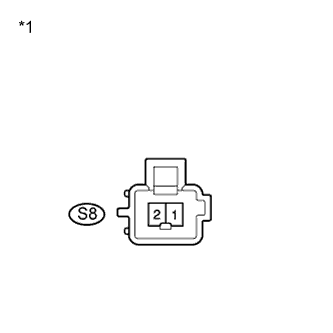
Text in Illustration *1 Front view of wire harness connector
(to Starter Relay Assembly)
Disconnect the starter relay connector.
-
Measure the voltage according to the value(s) in the table below.
Standard Voltage Tester Connection Condition Specified Condition S8-1 - S8-2 Engine cranking 18 to 27 V -
Reconnect the starter relay connector.
NG
INSPECT STARTER RELAY ASSEMBLY Click here
OK 
-
-
CHECK HARNESS AND CONNECTOR (IGNITION SWITCH ASSEMBLY - ECM)
-
Disconnect the ignition switch assembly connector.
-
Disconnect the ECM connector.
-
Measure the resistance according to the value(s) in the table below.
Standard Resistance (Check for Open) Tester Connection Condition Specified Condition I6-3 (ST1) - E23-18 (STA) Always Below 1 Ω Standard Resistance (Check for Short) Tester Connection Condition Specified Condition I6-3 (ST1) or E23-18 (STA) - Body ground Always 10 kΩ or higher -
Reconnect the ignition switch assembly connector.
-
Reconnect the ECM connector.
NG 
REPAIR OR REPLACE HARNESS OR CONNECTOR (IGNITION SWITCH ASSEMBLY - ECM)
OK
REPLACE ECM Click here
-
-
INSPECT STARTER RELAY ASSEMBLY
-
Inspect the starter relay assembly Click here.
NG
REPLACE STARTER RELAY ASSEMBLY Click here
OK
-
-
INSPECT IGNITION SWITCH ASSEMBLY
-
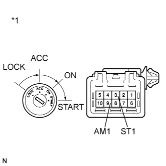
Text in Illustration *1 Component without harness connected
(Ignition Switch Assembly)
Disconnect the ignition switch assembly connector.
-
Measure the resistance according to the value(s) in the table below.
Standard Resistance Tester Connection Condition Specified Condition All terminals LOCK 10 kΩ or higher 9 (AM1) - 3 (ST1) START Below 1 Ω -
Reconnect the ignition switch assembly connector.
NG
REPLACE IGNITION SWITCH ASSEMBLY
OK
-
-
CHECK HARNESS AND CONNECTOR (IGNITION SWITCH ASSEMBLY - STARTER RELAY ASSEMBLY)
-
Disconnect the ignition switch assembly connector.
-
Disconnect the starter relay assembly connector.
-
Measure the resistance according to the value(s) in the table below.
Standard Resistance (Check for Open) Tester Connection Condition Specified Condition I6-3 (ST1) - S8-1 Always Below 1 Ω Standard Resistance (Check for Short) Tester Connection Condition Specified Condition I6-3 (ST1) or S8-1 - Body ground Always 10 kΩ or higher -
Reconnect the starter relay assembly connector.
-
Reconnect the ignition switch assembly connector.
NG
REPAIR OR REPLACE HARNESS OR CONNECTOR (IGNITION SWITCH ASSEMBLY - STARTER RELAY ASSEMBLY)
OK
-
-
CHECK HARNESS AND CONNECTOR (STARTER RELAY ASSEMBLY - BODY GROUND)
-
Disconnect the starter relay assembly connector.
-
Measure the resistance according to the value(s) in the table below.
Standard Resistance Tester Connection Condition Specified Condition S8-2 - Body ground Always Below 1 Ω -
Reconnect the starter relay assembly connector.
NG
REPAIR OR REPLACE HARNESS OR CONNECTOR (STARTER RELAY ASSEMBLY - BODY GROUND)
OK
REPAIR OR REPLACE HARNESS OR CONNECTOR (BATTERY - IGNITION SWITCH ASSEMBLY)
-