ECD SYSTEM Pre-heating Control Circuit
DESCRIPTION
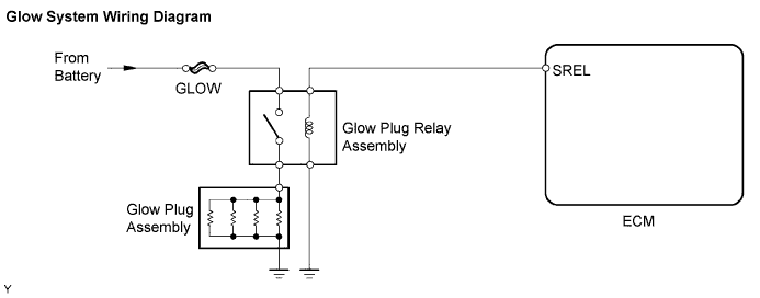
The glow plug assembly is mounted inside the engine combustion chamber. To ensure efficient engine starting with a cold engine, the ECM calculates a time interval of the current that needs to flow through the glow plug depending on the starting engine coolant temperature when the ignition switch is turned to ON. The ECM then turns on the glow plug relay assembly and permits the current to flow through the glow plug based on the ECM's calculated time. The glow plug relay assembly is then heated, and enhances fuel combustion with a cold engine.
This DTC will be set if the glow plug or the circuit is open.
Tech Tips
-
These troubleshooting procedures are for: 1) difficult starting engine in cold weather, and 2) difficult driving/vehicle malfunctions in cold weather immediately after the engine is started.
-
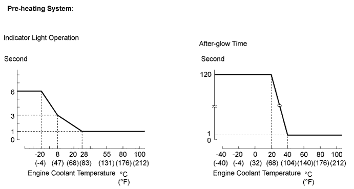
After the engine is started, the ECM performs an "after-glow" for a certain period of time. In proportion to the actual engine coolant temperature, the time period varies. The after-glow reduces diesel engine knocking, white smoke emissions and engine noises when the engine is cold.
INSPECTION PROCEDURE
Note
Inspect the fuses for circuits related to this system before performing the following inspection procedure.
PROCEDURE
-
CHECK GLOW INDICATOR LIGHT (ILLUMINATED)
-
Turn the ignition switch to ON.
-
Check if the glow indicator is illuminated.
OK Glow indicator light is illuminated for 0.5 seconds or more.
NG 
CHECK HARNESS AND CONNECTOR (ECM - COMBINATION METER ASSEMBLY) Click here
OK 
-
-
CHECK GLOW INDICATOR LIGHT (ILLUMINATED TIME)
-
Turn the ignition switch to ON.
-
Check the period that the glow indicator light is illuminated.
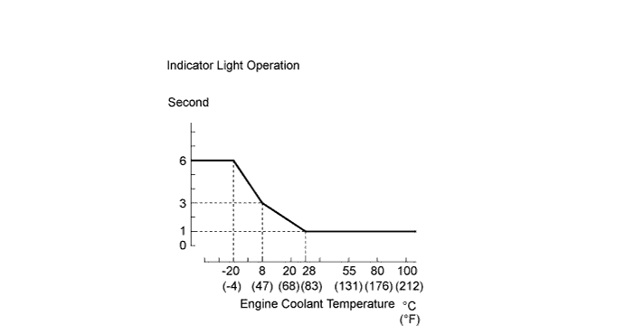
OK The glow indicator light is illuminated according to the engine coolant temperature as shown in the graph. Tech Tips
Glow plug operation varies depending on the engine coolant temperature.
NG
INSPECT ENGINE COOLANT TEMPERATURE SENSOR Click here
OK
-
-
CHECK ECM (SREL VOLTAGE)
-
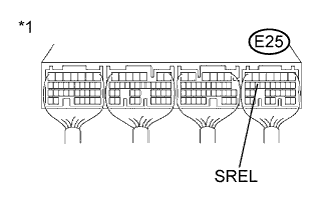
Text in Illustration *1 Component with harness connected
(ECM)
Start the engine.
-
Measure the voltage according to the value(s) in the table below.
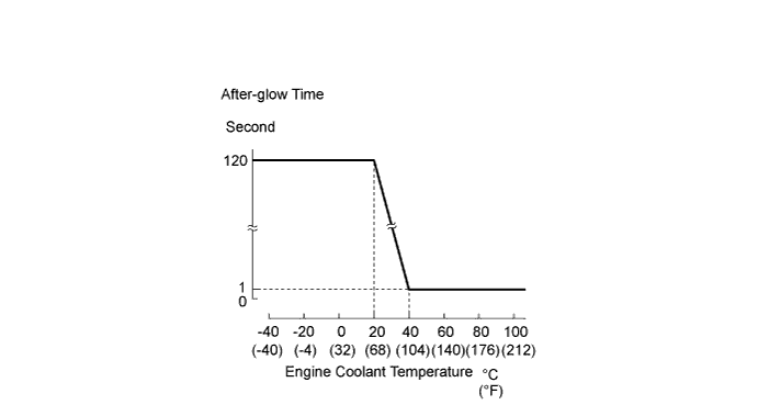
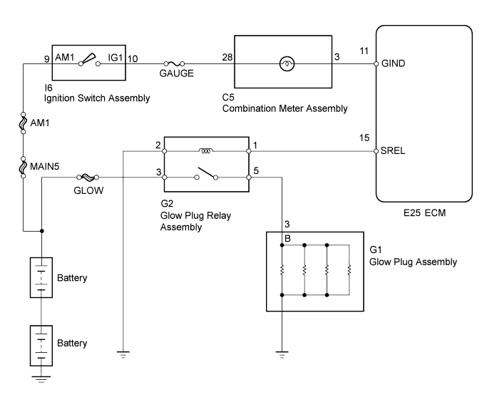
Standard Voltage Tester Connection Condition Specified Condition E25-15 (SREL) - Body ground Engine idling and after glow on 11 to 14 V E25-15 (SREL) - Body ground Engine idling and after glow off 0 to 2 V OK The after-glow operated according to the engine coolant temperature as shown in the graph. Tech Tips
After-glow operation varies depending on the engine coolant temperature.
NG
INSPECT ENGINE COOLANT TEMPERATURE SENSOR Click here
OK
-
-
INSPECT GLOW PLUG RELAY ASSEMBLY
-
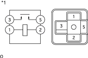
Text in Illustration *1 Component without harness connected
(Glow Plug Relay Assembly)
Remove the glow plug relay assembly from the No. 2 relay block.
-
Measure the resistance according to the value(s) in the table below.
Standard Resistance Tester Connection Condition Specified Condition 3 - 5 No battery voltage applied to terminals 1 and 2 10 kΩ or higher 3 - 5 Battery voltage applied to terminals 1 and 2 Below 1 Ω -
Reinstall the glow plug relay assembly.
NG 
REPLACE GLOW PLUG RELAY ASSEMBLY
OK
-
-
INSPECT GLOW PLUG ASSEMBLY
-
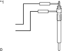
Text in Illustration *1 Component without harness connected
(Glow Plug Assembly)
Remove the glow plug assembly.
-
Measure the resistance according to the value(s) in the table below.
Standard Resistance Tester Connection Condition Specified Condition Glow plug terminal - Body ground 20°C (68°F) 2.7 to 3.5 Ω -
Reinstall the glow plug assembly.
NG
REPLACE GLOW PLUG ASSEMBLY Click here
OK
-
-
CHECK GLOW PLUG ASSEMBLY (INSTALLATION)
-
Check the glow plug assembly installation Click here.
OK The glow plug assemblies are installed securely.
NG
SECURELY REINSTALL GLOW PLUG ASSEMBLY Click here
OK
-
-
CHECK GLOW PLUG RELAY ASSEMBLY (POWER SOURCE)
-
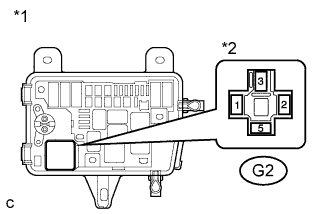
Text in Illustration *1 No. 2 Relay Block *2 Front view of wire harness connector
(to Glow Plug Relay Assembly)
Remove the glow plug relay assembly from the No. 2 relay block.
-
Measure the voltage according to the value(s) in the table below.
Standard Voltage Tester Connection Condition Specified Condition G2-3 - Body ground Always 18 to 27 V -
Reinstall the glow plug relay assembly.
NG
REPAIR OR REPLACE HARNESS OR CONNECTOR (GLOW PLUG RELAY ASSEMBLY - BATTERY)
OK
-
-
CHECK HARNESS AND CONNECTOR (GLOW PLUG RELAY ASSEMBLY - GLOW PLUG ASSEMBLY)
-
Remove the glow plug relay assembly from the No. 2 relay block.
-
Remove the glow plug connector.
-
Measure the resistance according to the value(s) in the table below.
Standard Resistance (Check for Open) Tester Connection Condition Specified Condition G2-5 - G1-3 Always Below 1 Ω Standard Resistance (Check for Short) Tester Connection Condition Specified Condition G2-5 or G1-3 - Body ground Always 10 kΩ or higher -
Reinstall the glow plug connector.
-
Reinstall the glow plug relay assembly.
NG
REPAIR OR REPLACE HARNESS OR CONNECTOR (GLOW PLUG RELAY ASSEMBLY - GLOW PLUG ASSEMBLY)
OK
-
-
CHECK HARNESS AND CONNECTOR (GLOW PLUG RELAY ASSEMBLY - ECM)
-
Remove the glow plug relay assembly from the No. 2 relay block.
-
Disconnect the ECM connector.
-
Measure the resistance according to the value(s) in the table below.
Standard Resistance (Check for Open) Tester Connection Condition Specified Condition G2-1 - E25-15 (SREL) Always Below 1 Ω Standard Resistance (Check for Short) Tester Connection Condition Specified Condition G2-1 or E25-15 (SREL) - Body ground Always 10 kΩ or higher -
Reconnect the ECM connector.
-
Reinstall the glow plug relay assembly.
NG
REPAIR OR REPLACE HARNESS OR CONNECTOR (GLOW PLUG RELAY ASSEMBLY - ECM)
OK
-
-
CHECK HARNESS AND CONNECTOR (GLOW PLUG RELAY ASSEMBLY - BODY GROUND)
-
Remove the glow plug relay assembly from the No. 2 relay block.
-
Measure the resistance according to the value(s) in the table below.
Standard Resistance Tester Connection Condition Specified Condition G2-2 - Body ground Always Below 1 Ω -
Reinstall the glow plug relay assembly.
NG
REPAIR OR REPLACE HARNESS OR CONNECTOR (GLOW PLUG RELAY ASSEMBLY - BODY GROUND)
OK 
PROCEED TO NEXT SUSPECTED AREA SHOWN IN PROBLEM SYMPTOMS TABLE Click here
-
-
CHECK HARNESS AND CONNECTOR (ECM - COMBINATION METER ASSEMBLY)
-
Disconnect the ECM connector.
-
Disconnect the combination meter assembly connector.
-
Measure the resistance according to the value(s) in the table below.
Standard Resistance (Check for Open) Tester Connection Condition Specified Condition E25-11 (GIND) - C5-3 Always Below 1 Ω Standard Resistance (Check for Short) Tester Connection Condition Specified Condition E25-11 (GIND) or C5-3 - Body ground Always 10 kΩ or higher -
Reconnect the combination meter assembly connector.
-
Reinstall the ECM connector.
NG
REPAIR OR REPLACE HARNESS OR CONNECTOR (ECM - COMBINATION METER ASSEMBLY)
OK
-
-
CHECK HARNESS AND CONNECTOR (COMBINATION METER ASSEMBLY - IGNITION SWITCH ASSEMBLY)
-
Disconnect the combination meter assembly connector.
-
Disconnect the ignition switch assembly connector.
-
Measure the resistance according to the value(s) in the table below.
Standard Resistance (Check for Open) Tester Connection Condition Specified Condition C5-28 - I6-10 (IG1) Always Below 1 Ω Standard Resistance (Check for Short) Tester Connection Condition Specified Condition C5-28 or I6-10 (IG1) - Body ground Always 10 kΩ or higher -
Reconnect the combination meter assembly connector.
-
Reinstall the ignition switch assembly connector.
NG
REPAIR OR REPLACE HARNESS OR CONNECTOR (COMBINATION METER ASSEMBLY - IGNITION SWITCH ASSEMBLY)
OK
-
-
INSPECT IGNITION SWITCH ASSEMBLY
-
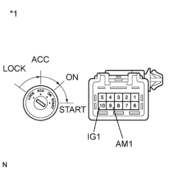
Text in Illustration *1 Component without harness connected
(Ignition Switch Assembly)
Disconnect the ignition switch assembly connector.
-
Measure the resistance according to the value(s) in the table below.
Standard Resistance Tester Connection Condition Specified Condition All terminals LOCK 10 kΩ or higher 9 (AM1) - 10 (IG1) ON Below 1 Ω -
Reconnect the ignition switch assembly connector.
NG
REPLACE IGNITION SWITCH ASSEMBLY
OK
-
-
CHECK IGNITION SWITCH ASSEMBLY (AM1 VOLTAGE)
-
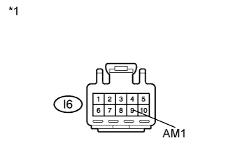
Text in Illustration *1 Front view of wire harness connector
(to Ignition Switch Assembly)
Disconnect the ignition switch assembly connector.
-
Measure the voltage according to the value(s) in the table below.
Standard Voltage Tester Connection Condition Specified Condition I6-9 (AM1) - Body ground Always 18 to 27 V -
Reinstall the ignition switch assembly connector.
NG
REPAIR OR REPLACE HARNESS OR CONNECTOR (IGNITION SWITCH ASSEMBLY - BATTERY)
OK
REPLACE COMBINATION METER ASSEMBLY
-
-
INSPECT ENGINE COOLANT TEMPERATURE SENSOR
-
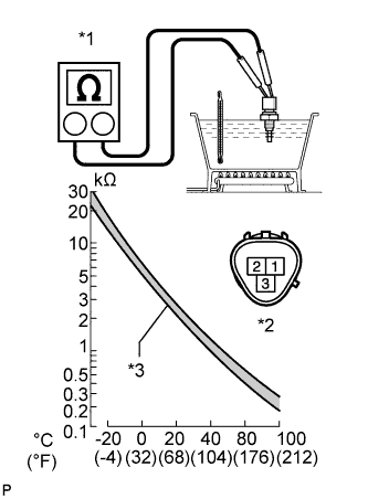
Text in Illustration *1 Ohmmeter *2 Engine Coolant Temperature Sensor *3 Acceptable Remove the engine coolant temperature sensor.
-
Measure the resistance according to the value(s) in the table below.
Standard Resistance Tester Connection Condition Specified Condition 1 - 2 20°C (68°F) 2.32 to 2.59 kΩ 1 - 2 80°C (176°F) 0.31 to 0.326 kΩ Note
When checking the sensor in water, keep the terminals dry. After the check, wipe the sensor dry.
Tech Tips
Alternative procedure: Connect an ohmmeter to the installed engine coolant temperature sensor and read the resistance. Use an infrared thermometer to measure the engine temperature in the immediate vicinity of the sensor. Compare these values with the resistance/ temperature graph. Change the engine temperature (warm up or cool down) and repeat the test.
-
Reinstall the engine coolant temperature sensor.
NG
REPLACE ENGINE COOLANT TEMPERATURE SENSOR Click here
OK
REPLACE ECM Click here
-