ECD SYSTEM, Diagnostic DTC:P2BAC

| DTC Code | DTC Name |
|---|---|
| P2BAC | NOx Exceedance - Deactivation of EGR |
DESCRIPTION
The EGR system recirculates exhaust gases, in order to suit every driving condition. The recirculated gas mingles with intake air, therefore the EGR system can slow combustion speed and keep the combustion temperature down. This helps reduce NOx emission.
In order to increase EGR circulation efficiency, the ECM adjusts the lift amount of the EGR valve assembly and throttle valve angle.
| DTC No. | DTC Detection Condition | Trouble Area |
|---|---|---|
| P2BAC | When following conditions (a) and (b) are met: (1 trip detection logic) (a) Battery voltage is 19.9 V or more (b) One of the following conditions (1), (2) or (3) is met (1) Open or short in EGR valve assembly circuit (2) Open or short in EGR valve position sensor circuit (3) EGR position out of specified threshold and battery voltage 10 V or more |
|
MONITOR DESCRIPTION
When the target and actual positions of the EGR valve assembly are different, the ECM interprets this as a malfunction of the EGR valve assembly and illuminates the MIL.
WIRING DIAGRAM
Refer to DTC P0405 Click here.
INSPECTION PROCEDURE
Note
After replacing the ECM, the new ECM needs registration Click here and initialization Click here.
Tech Tips
-
When this DTC is stored the vehicle enters fail-safe mode, in which the MIL blinks and the ECM measures elapsed time until an idle signal has been input or engine speed is below 200 rpm after 36 hours, after which engine output is limited to 75%.
-
Read freeze frame data using the intelligent tester. The ECM records vehicle and driving condition information as freeze frame data the moment a DTC is stored. When troubleshooting, freeze frame data can be helpful in determining whether the vehicle was moving or stationary, whether the engine was warmed up or not, as well as other data recorded at the time of a malfunction.
PROCEDURE
-
CHECK ANY OTHER DTCS OUTPUT (IN ADDITION TO DTC P2BAC)
-
Replace the normal DLC3 cable (12 V specification) for the intelligent tester with the 24 V DLC3 cable.
Note
Be sure to use the 24 V DLC3 cable when connecting the intelligent tester to the DLC3. Using the normal DLC3 cable (12 V specification) will cause damage to the tester.
-
Connect the intelligent tester to the DLC3.
-
Turn the ignition switch to ON and turn the tester on.
-
Enter the following menus: Powertrain / Engine and ECT / DTC.
-
Read the DTCs.
Result Result Proceed To DTC P2BAC is output A DTC P2BAC and other DTCs are output B Tech Tips
If any DTCs other than P2BAC are output, troubleshoot those DTCs first.
B 
GO TO DTC CHART Click here
A 
-
-
PERFORM ACTIVE TEST USING INTELLIGENT TESTER (CONTROL THE EGR SYSTEM)
-
Turn the ignition switch off and wait for 60 seconds.
-
Replace the normal DLC3 cable (12 V specification) for the intelligent tester with the 24 V DLC3 cable.
Note
Be sure to use the 24 V DLC3 cable when connecting the intelligent tester to the DLC3. Using the normal DLC3 cable (12 V specification) will cause damage to the tester.
-
Connect the intelligent tester to the DLC3.
-
Start the engine and turn the tester on.
-
Warm up the engine until the engine coolant temperature reaches 80°C (176°F).
-
Enter the following menus: Powertrain / Engine and ECT / Active Test / Control the EGR Step Position / Data List / MAF.
-
Read the value.
Result Active Test Result Proceed to 0 to 100% MAF value is not changed A MAF value is changed B Note
In the table below, the values listed under "MAF Value" are reference values. Do not depend solely on these reference values when deciding whether a part is faulty or not.
Reference EGR Valve Status Condition MAF Value Open (21%) Atmosphere pressure: 101 kPa
Intake air temperature: 25°C (77°F)
Engine coolant temperature: 76°C (169°F)
10 to 12 gm/sec Close (0%) 15 to 17 gm/sec
B 
INSPECT EGR VALVE ASSEMBLY (EGR VALVE OPERATION) Click here
A
-
-
INSPECT EGR VALVE ASSEMBLY
-
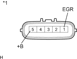
Text in Illustration *1 Component without harness connected
(EGR Valve Assembly)
Disconnect the EGR valve assembly connector.
-
Measure the resistance according to the value(s) in the table below.
Standard Resistance Tester Connection Condition Specified Condition 1 (EGR) - 5 (+B) 20°C (68°F) 6.5 to 7.5 Ω -
Reconnect the EGR valve assembly connector.
NG
REPLACE EGR VALVE ASSEMBLY Click here
OK
-
-
CHECK HARNESS AND CONNECTOR (EGR VALVE ASSEMBLY - ECM)
-
Disconnect the EGR valve assembly connector.
-
Disconnect the ECM connector.
-
Measure the resistance according to the value(s) in the table below.
Standard Resistance (Check for Open) Tester Connection Condition Specified Condition E23-3 (EGRS) - E17-1 (EGR) Always Below 1 Ω Standard Resistance (Check for Short) Tester Connection Condition Specified Condition E23-3 (EGRS) or E17-1 (EGR) - Body ground Always 10 kΩ or higher -
Reconnect the EGR valve assembly connector.
-
Reconnect the ECM connector.
NG
REPAIR OR REPLACE HARNESS OR CONNECTOR (EGR VALVE ASSEMBLY - ECM)
OK
-
-
CHECK EGR VALVE ASSEMBLY (POWER SOURCE)
-
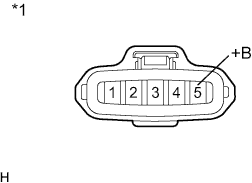
Text in Illustration *1 Front view of wire harness connector
(to EGR Valve Assembly)
Disconnect the EGR valve assembly connector.
-
Turn the ignition switch to ON.
-
Measure the voltage according to the value(s) in the table below.
Standard Voltage Tester Connection Switch Condition Specified Condition E17-5 (+B) - Body ground Ignition switch ON 11 to 14 V -
Reconnect the EGR valve assembly connector.
NG
REPAIR OR REPLACE HARNESS OR CONNECTOR (EGR VALVE ASSEMBLY - ENG-3 RELAY)
OK
-
-
INSPECT EGR VALVE ASSEMBLY (EGR VALVE OPERATION)
-
Remove the EGR valve assembly.
-
Inspect the EGR valve assembly.
-
Visually check the EGR valve assembly for deposits.
OK No deposits around the EGR valve. -
Visually check that there is no gap between the valve and body.
OK No gap between the valve and body. Result Result Proceed To NG A OK B
-
-
Reinstall the EGR valve assembly.
B
CHECK FOR BLOCKAGE IN EGR GAS PASSAGE (EXHAUST MANIFOLD - EGR COOLER - EGR VALVE ASSEMBLY) Click here
A
-
-
REPLACE EGR VALVE ASSEMBLY
-
Replace the EGR valve assembly Click here.
NEXT
-
-
CHECK FOR BLOCKAGE IN EGR GAS PASSAGE (EXHAUST MANIFOLD - EGR COOLER - EGR VALVE ASSEMBLY)
-
Check for blockage in the EGR gas passage from the exhaust manifold, through the EGR cooler sub-assembly to the EGR valve assembly.
OK No blockage in the EGR gas passage. Result Result Proceed To NG A OK B
B
CHECK WHETHER DTC OUTPUT RECURS Click here
A
-
-
REPAIR OR REPLACE MALFUNCTIONING PARTS, COMPONENT AND AREA
-
Repair or replace the malfunctioning parts, component and area.
NEXT
-
-
CHECK WHETHER DTC OUTPUT RECURS
-
Replace the normal DLC3 cable (12 V specification) for the intelligent tester with the 24 V DLC3 cable.
Note
Be sure to use the 24 V DLC3 cable when connecting the intelligent tester to the DLC3. Using the normal DLC3 cable (12 V specification) will cause damage to the tester.
-
Connect the intelligent tester to the DLC3.
-
Turn the ignition switch to ON and turn the tester on.
-
Start the engine and warm it up until the engine coolant temperature reaches 80°C (176°F).
-
Drive the vehicle at 50 km/h (31 mph) or more and then fully release the accelerator pedal for 5 seconds or more (Procedure "A").
-
Repeat procedure "A" several times.
-
Enter the following menus: Powertrain / Engine and ECT / DTC.
-
Read the DTC.
Result Result Proceed To DTC P2BAC is output A DTC is not output B
B
END
A 
REPLACE ECM
-
-
REPLACE ECM
-
Replace the EGR cooler sub-assembly.
-