ECD SYSTEM, Diagnostic DTC:P1674

| DTC Code | DTC Name |
|---|---|
| P1674 | Solenoid for Exhaust Brake Circuit Malfunction |
DESCRIPTION
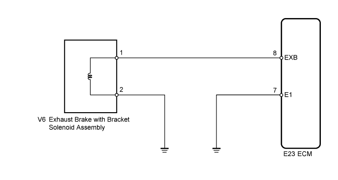
The exhaust brake with bracket solenoid assembly, opens and closes according to the signals from the ECM. The ECM receives the signals from the exhaust retarder switch assembly. Through the exhaust brake with bracket solenoid assembly, the ECM controls the negative pressure applied to the exhaust retarder assembly.
| DTC No. | DTC Detection Condition | Trouble Area |
|---|---|---|
| P1674 | Open or short in exhaust brake solenoid circuit for more than 3 seconds with clutch pedal released |
|
WIRING DIAGRAM
INSPECTION PROCEDURE
Tech Tips
Read freeze frame data using the intelligent tester. The ECM records vehicle and driving condition information as freeze frame data the moment a DTC is stored. When troubleshooting, freeze frame data can be helpful in determining whether the vehicle was moving or stationary, whether the engine was warmed up or not, as well as other data recorded at the time of a malfunction.
PROCEDURE
-
CHECK ECM (EXB VOLTAGE)
-
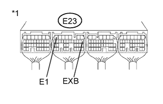
Text in Illustration *1 Component with harness connected
(ECM)
Turn the ignition switch to ON.
-
Measure the voltage according to the value(s) in the table below.
Standard Voltage Tester Connection Condition Specified Condition E23-8 (EXB) - E23-7 (E1) Exhaust brake is operating 11 to 14 V
NG 
INSPECT EXHAUST BRAKE WITH BRACKET SOLENOID ASSEMBLY Click here
OK 
REPLACE ECM Click here
-
-
INSPECT EXHAUST BRAKE WITH BRACKET SOLENOID ASSEMBLY
-
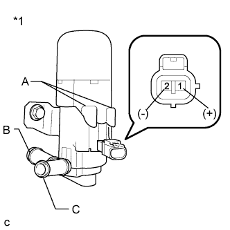
Text in Illustration *1 Component without harness connected
(Exhaust Brake with Bracket Solenoid Assembly)
Remove the exhaust brake with bracket solenoid assembly.
-
Check operation of the exhaust brake with bracket solenoid assembly.
Result Port Connection Specified Condition A - B Air does not flow B - C Air flows
(when battery voltage is applied to terminals 1 and 2)
A - C Air flows A - C Air does not flow
(when battery voltage is applied to terminals 1 and 2)
NG 
REPLACE EXHAUST BRAKE WITH BRACKET SOLENOID ASSEMBLY
OK 
-
-
CHECK HARNESS AND CONNECTOR (ECM - EXHAUST BRAKE WITH BRACKET SOLENOID ASSEMBLY)
-
Disconnect the exhaust brake with bracket solenoid assembly connector.
-
Disconnect the ECM connector.
-
Measure the resistance according to the value(s) in the table below.
Standard Resistance (Check for Open) Tester Connection Condition Specified Condition V6-1 - E23-8 (EXB) Always Below 1 Ω Standard Resistance (Check for Short) Tester Connection Condition Specified Condition V6-1 or E23-8 (EXB) - Body ground Always 10 kΩ or higher -
Reconnect the exhaust brake with bracket solenoid assembly connector.
-
Reconnect the ECM connector.
NG
REPAIR OR REPLACE HARNESS OR CONNECTOR (ECM - EXHAUST BRAKE WITH BRACKET SOLENOID ASSEMBLY)
OK
REPLACE ECM Click here
-