ECD SYSTEM, Diagnostic DTC:P0544, P0545, P0546

| DTC Code | DTC Name |
|---|---|
| P0544 | Exhaust GAS Temperature Sensor Circuit (Bank 1 Sensor 1) |
| P0545 | Exhaust Gas Temperature Sensor Circuit Low (Bank 1 Sensor 1) |
| P0546 | Exhaust Gas Temperature Sensor Circuit High (Bank 1 Sensor 1) |
DESCRIPTION
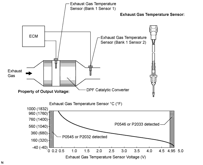
The exhaust gas temperature sensors are installed in front of and behind the DPF (*1) catalytic converter to sense the exhaust gas temperature.
A thermistor built into the sensor changes its resistance value according to the exhaust gas temperature. The lower the exhaust gas temperature becomes, the greater the thermistor resistance value becomes. The exhaust gas temperature becomes, the lower the thermistor resistance value becomes.
The higher the exhaust gas temperature sensor is connected to the ECM. The 5 V power source voltage in the ECM is applied to the exhaust gas temperature sensor from terminals THCI (bank 1 sensor 1) and THCO (bank 1 sensor 2) via resistor R.
The resistor R and the exhaust gas temperature sensor are connected in series. When the resistance value of the exhaust gas temperature sensor changes in accordance with changes in the exhaust gas temperature, the voltage at terminals THCI (bank 1 sensor 1) and THCO (bank 1 sensor 2) also changes. Based on these signals, when DPF catalyst regeneration is needed, the ECM operates the injector to obtain target upstream temperature of the DPF catalytic converter as monitored through sensor 1. In addition, the ECM monitors the rate of DPF catalytic converter temperature increase using sensor 2.
*1: Diesel Particulate Filter
| DTC No. | DTC Detection Condition | Trouble Area |
|---|---|---|
| P0544 | Sensor 1 output is less than 0.2 V or more than 4.95 V for 8 seconds or more (1 trip detection logic) |
|
| P0545 | Sensor 1 output is less than 0.2 V for 8 seconds or more (1 trip detection logic) |
|
| P0546 | Sensor 1 output is more than 4.95 V for 8 seconds or more (1 trip detection logic) |
|
Tech Tips
-
Sensor 1 represents a sensor located upstream of the DPF catalytic converter.
-
Sensor 2 represents a sensor located downstream of the DPF catalytic converter.
-
After confirming DTC P0544, P0545, P0546, P2031, P2032, and P2033, check the upstream and downstream exhaust gas temperature by selecting the following menus on the tester: Powertrain / Engine and ECT / Exhaust Temperature B1S1 and Exhaust Temperature B2S1.
Result Condition Exhaust Gas Temperature Exhaust Gas Temperature Sensor Condition Idling after warm-up Constant at 50 to 700°C (122 to 1292°F) Normal 0°C (32°F) Open circuit 1000°C (1832°F) Short circuit
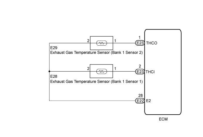
WIRING DIAGRAM
INSPECTION PROCEDURE
Note
After replacing the ECM, the new ECM needs registration Click here and initialization Click here.
PROCEDURE
-
READ VALUE USING INTELLIGENT TESTER (EXHAUST GAS TEMPERATURE)
-
Replace the normal DLC3 cable (12 V specification) for the intelligent tester with the 24 V DLC3 cable.
Note
Be sure to use the 24 V DLC3 cable when connecting the intelligent tester to the DLC3. Using the normal DLC3 cable (12 V specification) will cause damage to the tester.
-
Connect the intelligent tester to the DLC3.
-
Turn the ignition switch to ON.
-
Turn the tester on.
-
Enter the following menus: Powertrain / Engine and ECT / Exhaust Temperature B1S1.
-
Read the value.
Standard Same as the actual exhaust gas temperature (50 to 700°C [122 to 1292°F] during idling after warm-up), and varies after an engine speed of 3000 rpm is maintained for 1 minute. Result Temperature Displayed Proceed to 0°C (32°F) (After warming up the engine) A 1000°C (1832°F) B OK: Same as the actual exhaust gas temperature (50 to 700°C [122 to 1292°F] during idling after warm-up), and varies after maintaining the engine speed of 3000 rpm for 1 minute after accelerating the engine from idling to 3000 rpm C Tech Tips
-
If there is an open circuit, the intelligent tester will indicate 0°C (32°F).
-
If there is a short circuit, the intelligent tester will indicate 1000°C (1832°F).
-
B 
READ VALUE USING INTELLIGENT TESTER (SHORT IN WIRE HARNESS) Click here
C 
CHECK FOR INTERMITTENT PROBLEMS Click here
A 
-
-
READ VALUE USING INTELLIGENT TESTER (OPEN IN WIRE HARNESS)
-
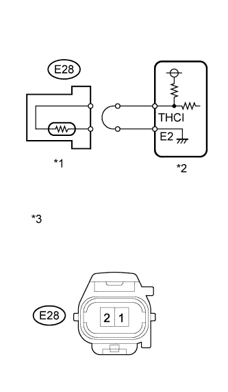
Text in Illustration *1 Exhaust Gas Temperature Sensor
(Bank 1 Sensor 1)
*2 ECM *3 Front view of wire harness connector
(to Exhaust Gas Temperature Sensor (Bank 1 Sensor 1))
Disconnect the exhaust gas temperature sensor (bank 1 sensor 1) connector.
-
Connect terminals 1 and 2 of the exhaust gas temperature sensor wire harness side connector.
-
Replace the normal DLC3 cable (12 V specification) for the intelligent tester with the 24 V DLC3 cable.
Note
Be sure to use the 24 V DLC3 cable when connecting the intelligent tester to the DLC3. Using the normal DLC3 cable (12 V specification) will cause damage to the tester.
-
Connect the intelligent tester to the DLC3.
-
Turn the ignition switch to ON.
-
Turn the tester on.
-
Enter the following menus: Powertrain / Engine and ECT / Exhaust Temperature B1S1.
-
Read the value.
Standard 1000°C (1832°F) -
Reconnect the exhaust gas temperature sensor (bank 1 sensor 1) connector.
NG
READ VALUE USING INTELLIGENT TESTER (OPEN IN ECM) Click here
OK 
REPLACE EXHAUST GAS TEMPERATURE SENSOR (BANK 1 SENSOR 1) Click here
-
-
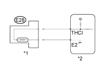
READ VALUE USING INTELLIGENT TESTER (OPEN IN ECM)
-
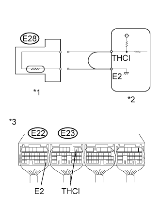
Text in Illustration *1 Exhaust Gas Temperature Sensor
(Bank 1 Sensor 1)
*2 ECM *3 Component with harness connected
(ECM)
Disconnect the exhaust gas temperature sensor (bank 1 sensor 1) connector.
-
Connect terminals THCI and E2 of the ECM connectors.
Tech Tips
Before checking, do a visual and contact pressure check on the ECM connector.
-
Replace the normal DLC3 cable (12 V specification) for the intelligent tester with the 24 V DLC3 cable.
Note
Be sure to use the 24 V DLC3 cable when connecting the intelligent tester to the DLC3. Using the normal DLC3 cable (12 V specification) will cause damage to the tester.
-
Connect the intelligent tester to the DLC3.
-
Turn the ignition switch to ON.
-
Turn the tester on.
-
Enter the following menus: Powertrain / Engine and ECT / Exhaust Temperature B1S1.
-
Read the value.
Standard 1000°C (1832°F) -
Reconnect the exhaust gas temperature sensor (bank 1 sensor 1) connector.
NG
REPLACE ECM Click here
OK
REPAIR OR REPLACE HARNESS OR CONNECTOR (ECM - EXHAUST GAS TEMPERATURE SENSOR)
-
-
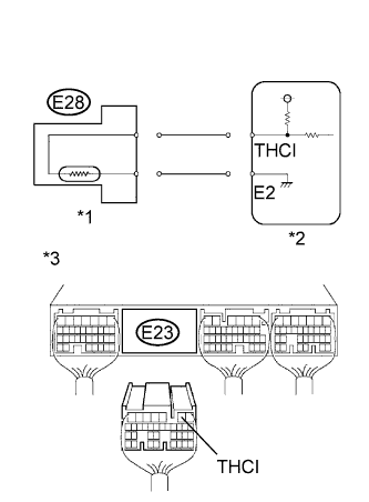
READ VALUE USING INTELLIGENT TESTER (SHORT IN WIRE HARNESS)
-
Text in Illustration *1 Exhaust Gas Temperature Sensor
(Bank 1 Sensor 1)
*2 ECM Disconnect the exhaust gas temperature sensor (bank 1 sensor 1) connector.
-
Replace the normal DLC3 cable (12 V specification) for the intelligent tester with the 24 V DLC3 cable.
Note
Be sure to use the 24 V DLC3 cable when connecting the intelligent tester to the DLC3. Using the normal DLC3 cable (12 V specification) will cause damage to the tester.
-
Connect the intelligent tester to the DLC3.
-
Turn the ignition switch to ON.
-
Turn the tester on.
-
Enter the following menus: Powertrain / Engine and ECT / Exhaust Temperature B1S1.
-
Read the value.
Standard 0°C (32°F) -
Reconnect the exhaust gas temperature sensor connector.
NG
READ VALUE USING INTELLIGENT TESTER (SHORT IN ECM) Click here
OK
REPLACE EXHAUST GAS TEMPERATURE SENSOR (BANK 1 SENSOR 1) Click here
-
-
READ VALUE USING INTELLIGENT TESTER (SHORT IN ECM)
-
Text in Illustration *1 Exhaust Gas Temperature Sensor
(Bank 1 Sensor 1)
*2 ECM *3 Rear view of wire harness connector
(to ECM)
Disconnect the exhaust gas temperature sensor (bank 1 sensor 1) connector.
-
Disconnect the ECM connector.
-
Replace the normal DLC3 cable (12 V specification) for the intelligent tester with the 24 V DLC3 cable.
Note
Be sure to use the 24 V DLC3 cable when connecting the intelligent tester to the DLC3. Using the normal DLC3 cable (12 V specification) will cause damage to the tester.
-
Connect the intelligent tester to the DLC3.
-
Turn the ignition switch to ON.
-
Turn the tester on.
-
Enter the following menus: Powertrain / Engine and ECT / Exhaust Temperature B1S1.
-
Read the value.
Standard 0°C (32°F) -
Reconnect the exhaust gas temperature sensor (bank 1 sensor 1) connector.
-
Reconnect the ECM connector.
NG
REPLACE ECM Click here
OK
REPAIR OR REPLACE HARNESS OR CONNECTOR (ECM - EXHAUST GAS TEMPERATURE SENSOR)
-