ECD SYSTEM, Diagnostic DTC:P0560

| DTC Code | DTC Name |
|---|---|
| P0560 | System Voltage |
DESCRIPTION
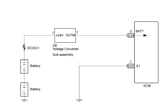
While the ignition switch is off, battery voltage is supplied to terminal BATT of the ECM for storing DTCs and fuel injection feedback learning values.
| DTC No. | DTC Detection Condition | Trouble Area |
|---|---|---|
| P0560 | Condition (a) or (b) continues: (a) Significant decrease in battery voltage (b) Open in back-up power source circuit (1 trip detection logic) |
|
Tech Tips
If DTC P0560 appears, the ECM does not store other DTCs.
WIRING DIAGRAM
INSPECTION PROCEDURE
PROCEDURE
-
CHECK ECM (BATT VOLTAGE)
-
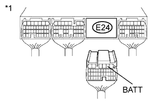
Text in Illustration *1 Rear view of wire harness connector
(to ECM)
Disconnect the ECM connector.
-
Measure the voltage according to the value(s) in the table below.
Standard Voltage Tester Connection Condition Specified Condition E24-2 (BATT) - Body ground Always 11 to 14 V -
Reconnect the ECM connector.
NG 
CHECK HARNESS AND CONNECTOR (ECM - VOLTAGE CONVERTER SUB-ASSEMBLY) Click here
OK 
CHECK FOR INTERMITTENT PROBLEMS Click here
-
-
CHECK HARNESS AND CONNECTOR (ECM - VOLTAGE CONVERTER SUB-ASSEMBLY)
-
Disconnect the voltage converter sub-assembly connector.
-
Disconnect the ECM connector.
-
Measure the resistance according to the value(s) in the table below.
Standard Resistance (Check for Open) Tester Connection Condition Specified Condition E24-2 (BATT) - D8-7 (OUTM) Always Below 1 Ω Standard Resistance (Check for Short) Tester Connection Condition Specified Condition E24-2 (BATT) or D8-7 (OUTM) - Body ground Always 10 kΩ or higher -
Reconnect the ECM connector.
-
Reconnect the voltage converter sub-assembly connector.
NG 
REPAIR OR REPLACE HARNESS OR CONNECTOR (ECM - VOLTAGE CONVERTER SUB-ASSEMBLY)
OK 
-
-
INSPECT BATTERY
-
Check that the battery is not depleted.
OK Battery is not depleted.
NG
REPAIR OR REPLACE BATTERY
OK
REPLACE VOLTAGE CONVERTER SUB-ASSEMBLY Click here
-