ECD SYSTEM, Diagnostic DTC:P0340

| DTC Code | DTC Name |
|---|---|
| P0340 | Camshaft Position Sensor "A" Circuit (Bank 1 or Single Sensor) |
DESCRIPTION
The camshaft position sensor (G signal) consists of a magnet and MR element.
The camshaft drive gear has 5 teeth on its inner circumference. When the camshaft drive gear rotates, air gap changes between the protrusion on the gear and the pickup coil. The change affects the magnetic field and results in change in the resistance of the MR element. The crankshaft angle sensor plate has 32 teeth and output 32 signals every engine revolution. The ECM detects the standard crankshaft angle based on the G signal and actual crankshaft angle and engine speed by NE signal.
| DTC No. | DTC Detection Condition | Trouble Area |
|---|---|---|
| P0340 | STA ON: No camshaft position sensor signal to ECM while cranking for 4 seconds or more STA OFF: No camshaft position sensor signal to ECM with engine speed 650 to 3000 rpm 20 times or more |
|
WIRING DIAGRAM
Refer to DTC P0335 Click here.
INSPECTION PROCEDURE
Tech Tips
Read freeze frame data using the intelligent tester. The ECM records vehicle and driving condition information as freeze frame data the moment a DTC is stored. When troubleshooting, freeze frame data can be helpful in determining whether the vehicle was moving or stationary, whether the engine was warmed up or not, as well as other data recorded at the time of a malfunction.
PROCEDURE
-
CHECK CAMSHAFT POSITION SENSOR
-
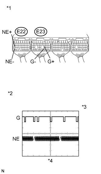
Text in Illustration *1 Component with harness connected
(ECM)
*2 G and NE Signal Waveforms *3 5 V/DIV. *4 20 ms./DIV. (Idling) While idling the engine, check the waveform of the ECM connectors using an oscilloscope.
Standard Tester Connection Specified Condition E22-27 (NE+) - E22-34 (NE-) Correct waveform appears as shown E23-23 (G+) - E23-31 (G-) Correct waveform appears as shown
NG 
CHECK ECM (VCG VOLTAGE) Click here
OK 
CHECK FOR INTERMITTENT PROBLEMS Click here
-
-
CHECK ECM (VCG VOLTAGE)
-
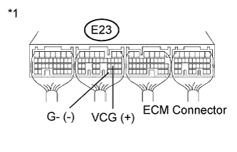
Text in Illustration *1 Component with harness connected
(ECM)
Turn the ignition switch to ON.
-
Measure the voltage according to the value(s) in the table below.
Standard Voltage Tester Connection Switch Condition Specified Condition E23-22 (VCG) - E23-31 (G-) Ignition switch ON 4.5 to 5.5 V
NG 
REPLACE ECM Click here
OK 
-
-
CHECK HARNESS AND CONNECTOR (CAMSHAFT POSITION SENSOR - ECM)
-
Disconnect the camshaft position sensor connector.
-
Disconnect the ECM connector.
-
Measure the resistance according to the value(s) in the table below.
Standard Resistance (Check for Open) Tester Connection Condition Specified Condition C1-1 (OUT) - E23-23 (G+) Always Below 1 Ω C1-2 (GND) - E23-31 (G-) Always Below 1 Ω C1-3 (VCC) - E23-22 (VCG) Always Below 1 Ω Standard Resistance (Check for Short) Tester Connection Condition Specified Condition C1-1 (OUT) or E23-23 (G+) - Body ground Always 10 kΩ or higher C1-2 (GND) or E23-31 (G-) - Body ground Always 10 kΩ or higher C1-3 (VCC) or E23-22 (VCG) - Body ground Always 10 kΩ or higher -
Reconnect the camshaft position sensor connector.
-
Reconnect the ECM connector.
NG
REPAIR OR REPLACE HARNESS OR CONNECTOR (CAMSHAFT POSITION SENSOR - ECM)
OK
-
-
CHECK CAMSHAFT POSITION SENSOR (SENSOR INSTALLATION)
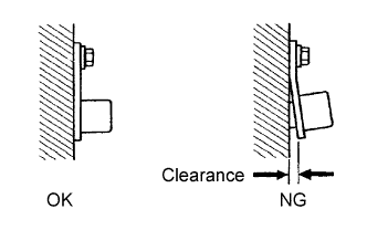
OK The camshaft position sensor is installed properly.
NG
SECURELY REINSTALL CAMSHAFT POSITION SENSOR
OK
-
INSPECT CAMSHAFT (CAMSHAFT DRIVE GEAR)
-
Check the teeth of the camshaft drive gear.
NG
REPLACE CAMSHAFT (CAMSHAFT DRIVE GEAR) Click here
OK
-
-
REPLACE CAMSHAFT POSITION SENSOR
-
Replace the camshaft position sensor Click here.
NEXT
-
-
CHECK DTC OUTPUT
-
Replace the normal DLC3 cable (12 V specification) for the intelligent tester with the 24 V DLC3 cable.
Note
Be sure to use the 24 V DLC3 cable when connecting the intelligent tester to the DLC3. Using the normal DLC3 cable (12 V specification) will cause damage to the tester.
-
Connect the intelligent tester to the DLC3.
-
Turn the ignition switch to ON.
-
Turn the tester on.
-
Enter the following menus: Powertrain / Engine and ECT / DTC.
-
Read the DTCs.
Result Result Proceed to DTC P0340 is output A DTC is not output B
B
END
A
REPLACE ECM Click here
-