ECD SYSTEM, Diagnostic DTC:P0263, P0266, P0269, P0272

| DTC Code | DTC Name |
|---|---|
| P0263 | Cylinder 1 Contribution / Balance |
| P0266 | Cylinder 2 Contribution / Balance |
| P0269 | Cylinder 3 Contribution / Balance |
| P0272 | Cylinder 4 Contribution / Balance |
DESCRIPTION
The ECM controls the fuel injection compensation volume when the engine is idling.
If excessive deposits are present in an injector assembly, it may lower the fuel injection volume, resulting in an engine that stalls or has an unstable idle. Therefore, the ECM increases the fuel injection compensation volume to ensure the fuel injection volume necessary for idling.
The ECM stores this DTC if the fuel injection compensation volume exceeds the specified value.
| DTC No. | DTC Detection Condition | Trouble Area |
|---|---|---|
| P0263 P0266 P0269 P0272 |
Conditions (a) and (b) are met more than 200 times with engine speed 500 to 1000 rpm (1 trip detection logic): (a) Engine coolant temperature: 60°C (140°F) or more (b) Difference of compensation value between cylinders: 15 mm3/sec. or more |
|
Tech Tips
These DTCs indicate a malfunction related to the primary circuit.
-
If DTC P0263 is displayed, check the No. 1 injector circuit.
-
If DTC P0266 is displayed, check the No. 2 injector circuit.
-
If DTC P0269 is displayed, check the No. 3 injector circuit.
-
If DTC P0272 is displayed, check the No. 4 injector circuit.
WIRING DIAGRAM
Refer to DTC P0200 Click here.
INSPECTION PROCEDURE
Tech Tips
Read freeze frame data using the intelligent tester. The ECM records vehicle and driving condition information as freeze frame data the moment a DTC is stored. When troubleshooting, freeze frame data can be helpful in determining whether the vehicle was moving or stationary, whether the engine was warmed up or not, as well as other data recorded at the time of a malfunction.
PROCEDURE
-
CHECK ANY OTHER DTCS OUTPUT (IN ADDITION DTC P0263, P0266, P0269 AND P272)
-
Replace the normal DLC3 cable (12 V specification) for the intelligent tester with the 24 V DLC3 cable.
Note
Be sure to use the 24 V DLC3 cable when connecting the intelligent tester to the DLC3. Using the normal DLC3 cable (12 V specification) will cause damage to the tester.
-
Connect the intelligent tester to the DLC3.
-
Turn the ignition switch to ON, and turn the tester on.
-
Enter the following menus: Powertrain / Engine and ECT / DTC.
-
Read the DTCs.
Result Result Proceed to DTC P0263, P0266, P0269 and/or P0272 are output A DTC P0263, P0266, P0269 and/or P0272 and any other DTCs are output B
B 
GO TO DTC CHART Click here
A 
-
-
CHANGE TO KNOWN GOOD INJECTOR ASSEMBLY
-
Change the installed injector assembly to a known good injector assembly.
-
Input the injector compensation code Click here.
NEXT
-
-
CHECK WHETHER DTC OUTPUT RECURS (DTC P0263, P0266, P0269 AND P0272)
-
Replace the normal DLC3 cable (12 V specification) for the intelligent tester with the 24 V DLC3 cable.
Note
Be sure to use the 24 V DLC3 cable when connecting the intelligent tester to the DLC3. Using the normal DLC3 cable (12 V specification) will cause damage to the tester.
-
Connect the intelligent tester to the DLC3.
-
Turn the ignition switch to ON, and turn the tester on.
-
Clear the DTCs Click here.
-
Warm up the engine.
-
Enter the following menus: Powertrain / Engine and ECT / DTC.
-
Read the DTCs.
Result Result Proceed to Same DTCs are output (same as DTCs that were cleared) A Other DTCs are output B Tech Tips
-
If a DTC for a different cylinder is stored when the injector assembly has been switched with a known good one from a different cylinder, the injector assembly may be malfunctioning.
-
If no DTC is stored after the injector assembly has been replaced, the injector assembly may be malfunctioning.
-
If the same DTC is stored again even after replacing the injector assembly with a known good injector assembly, the ECM, injector driver assembly, engine or wire harness may be malfunctioning.
-
B 
CHECK MALFUNCTIONING CYLINDER'S INJECTOR ASSEMBLY FOR DEPOSITS Click here
A
-
-
CHECK INJECTOR DRIVER ASSEMBLY (INJECTOR ASSEMBLY RESISTANCE)
-
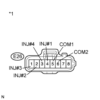
Text in Illustration *1 Front view of wire harness connector
(to Injector Driver Assembly)
Disconnect the injector driver assembly connector.
-
Measure the resistance according to the value(s) in the table below.
Standard Resistance Tester Connection Condition Specified Condition E26-4 (INJ#1) - E26-5 (COM1) 20°C (68°F) 0.35 to 0.57 Ω E26-2 (INJ#2) - E26-6 (COM2) 20°C (68°F) 0.35 to 0.57 Ω E26-1 (INJ#3) - E26-6 (COM2) 20°C (68°F) 0.35 to 0.57 Ω E26-3 (INJ#4) - E26-5 (COM1) 20°C (68°F) 0.35 to 0.57 Ω Result Result Proceed to NG A OK B -
Reconnect the injector driver assembly connector.
NG
INSPECT INJECTOR ASSEMBLY Click here
OK
-
-
CHECK HARNESS AND CONNECTOR (INJECTOR DRIVER ASSEMBLY - ECM)
-
Disconnect the injector driver assembly connector.
-
Disconnect the ECM connector.
-
Measure the resistance according to the value(s) in the table below.
Standard Resistance (Check for Open) Tester Connection Condition Specified Condition E27-6 (IJT#1) - E22-24 (#1) Always Below 1 Ω E27-3 (IJT#2) - E22-23 (#2) Always Below 1 Ω E27-2 (IJT#3) - E22-22 (#3) Always Below 1 Ω E27-5 (IJT#4) - E22-21 (#4) Always Below 1 Ω E27-7 (IJF) - E22-25 (INJF) Always Below 1 Ω Standard Resistance (Check for Short) Tester Connection Condition Specified Condition E27-6 (IJT#1) or E22-24 (#1) - Body ground Always 10 kΩ or higher E27-3 (IJT#2) or E22-23 (#2) - Body ground Always 10 kΩ or higher E27-2 (IJT#3) or E22-22 (#3) - Body ground Always 10 kΩ or higher E27-5 (IJT#4) or E22-21 (#4) - Body ground Always 10 kΩ or higher E27-7 (IJF) or E22-25 (INJF) - Body ground Always 10 kΩ or higher -
Reconnect the injector driver assembly connector.
-
Reconnect the ECM connector.
NG
REPAIR OR REPLACE HARNESS OR CONNECTOR (INJECTOR DRIVER ASSEMBLY - ECM)
OK
-
-
CHECK ECM (OUTPUT VOLTAGE)
-
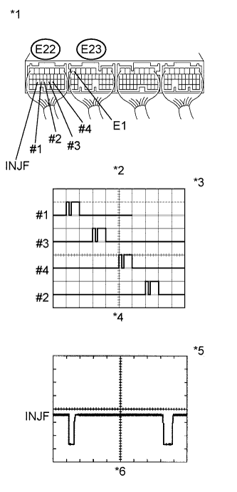
Text in Illustration *1 Component with harness connected
(ECM)
*2 Signal Waveform *3 5 V/DIV. *4 20 ms./DIV. *5 2 V/DIV. *6 1 ms./DIV. While idling the engine, check the waveform of the ECM connectors using an oscilloscope.
Standard Tester Connection Specified Condition E22-24 (#1) - E23-7 (E1) Correct waveform appears as shown E22-23 (#2) - E23-7 (E1) Correct waveform appears as shown E22-22 (#3) - E23-7 (E1) Correct waveform appears as shown E22-21 (#4) - E23-7 (E1) Correct waveform appears as shown E22-25 (INJF) - E23-7 (E1) Correct waveform appears as shown Result Result Proceed to #1 to #4 is normal, INJF is abnormal A #1 to #4 is abnormal, INJF is normal B #1 to #4 and INJF are normal C
B
REPLACE ECM Click here
C
CHECK CYLINDER COMPRESSION PRESSURE Click here
A 
REPLACE INJECTOR DRIVER ASSEMBLY Click here
-
-
CHECK CYLINDER COMPRESSION PRESSURE
-
Measure the cylinder compression pressure of the misfiring cylinder Click here.
NG
CHECK ENGINE TO DETERMINE CAUSE OF LOW COMPRESSION
OK
CHECK FOR INTERMITTENT PROBLEMS Click here
-
-
CHECK MALFUNCTIONING CYLINDER'S INJECTOR ASSEMBLY FOR DEPOSITS
-
Remove the injector assembly of the malfunctioning cylinder.
-
Check the injector assembly for any deposits.
Injector Assembly Condition Proceed to Deposits A No deposits B Tech Tips
If excessive deposits are present on the head of the injector assembly, a malfunction of something other than the injector assembly has resulted in an increase of the fuel injection compensation volume. First perform the troubleshooting procedure for black smoke.
B
REPLACE INJECTOR ASSEMBLY Click here
A
GO TO BLACK SMOKE EMITTED Click here
-
-
INSPECT INJECTOR ASSEMBLY
-
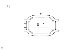
Text in Illustration *1 Component without harness connected
(Injector Assembly)
Disconnect the injector assembly connectors.
-
Measure the resistance according to the value(s) in the table below.
Standard Resistance Tester Connection Condition Specified Condition 1 - 2 20°C (68°F) 0.35 to 0.57 Ω -
Reconnect the injector assembly connectors.
NG
REPLACE INJECTOR ASSEMBLY Click here
OK
REPAIR OR REPLACE HARNESS OR CONNECTOR (INJECTOR DRIVER ASSEMBLY - INJECTOR ASSEMBLY)
-