ECD SYSTEM, Diagnostic DTC:P0110, P0112, P0113

| DTC Code | DTC Name |
|---|---|
| P0110 | Intake Air Temperature Circuit |
| P0112 | Intake Air Temperature Circuit Low Input |
| P0113 | Intake Air Temperature Circuit High Input |
DESCRIPTION
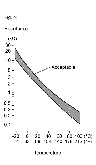
The intake air temperature sensor is built into the mass air flow meter sub-assembly and senses the atmospheric temperature. A thermistor built in the sensor changes the resistance value according to the intake air temperature. The lower the atmospheric temperature is, the greater the thermistor resistance value is, and the higher the atmospheric temperature is, the lower the thermistor resistance value is (see Fig. 1).
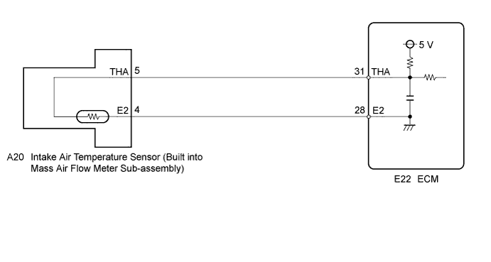
The intake air temperature sensor is connected to the ECM. The 5 V power source voltage in the ECM is applied to the intake air temperature sensor from terminal THA via a resistor R. The resistor R and the intake air temperature sensor are connected in series. When the resistance value of the intake air temperature sensor changes in accordance with changes in the intake air temperature, the voltage at terminal THA also changes. Based on this signal, the ECM increases the fuel injection volume to improve driveability during cold engine operation.
| DTC No. | Proceed to | DTC Detection Condition | Trouble Area |
|---|---|---|---|
| P0110 | Step 1 | Open or short in intake air temperature sensor circuit for 0.5 seconds |
|
| P0112 | Step 4 | Short in intake air temperature sensor circuit for 0.5 seconds |
|
| P0113 | Step 2 | Open in intake air temperature sensor circuit for 0.5 seconds |
|
Tech Tips
When DTC P0110, P0112 or P0113 is detected, check the intake air temperature by entering the following menus using the intelligent tester: Powertrain / Engine and ECT / Data List / Intake Air.
| Temperature Displayed | Malfunction |
|---|---|
| -40°C (-40°F) | Open circuit |
| 140°C (284°F) | Short circuit |
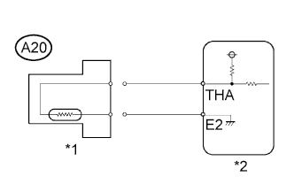
WIRING DIAGRAM
INSPECTION PROCEDURE
Note
After replacing the ECM, the new ECM needs registration Click here and initialization Click here.
Tech Tips
-
If DTCs that are related to different systems are output simultaneously while terminal E2 is used as a ground terminal, terminal E2 may have an open circuit.
-
Read freeze frame data using the intelligent tester. The ECM records vehicle and driving condition information as freeze frame data the moment a DTC is stored. When troubleshooting, freeze frame data can be helpful in determining whether the vehicle was moving or stationary, whether the engine was warmed up or not, as well as other data recorded at the time of a malfunction.
PROCEDURE
-
READ VALUE USING INTELLIGENT TESTER (INTAKE AIR TEMPERATURE)
-
Replace the normal DLC3 cable (12 V specification) for the intelligent tester with the 24 V DLC3 cable.
Note
Be sure to use the 24 V DLC3 cable when connecting the intelligent tester to the DLC3. Using the normal DLC3 cable (12 V specification) will cause damage to the tester.
-
Connect the intelligent tester to the DLC3.
-
Turn the ignition switch to ON.
-
Turn the tester on.
-
Enter the following menus: Powertrain / Engine and ECT / Data List / Intake Air.
-
Read the value.
Standard Same value as the actual inlet air temperature. Result Temperature Display Proceed to -40°C (-40°F) A 140°C (284°F) B OK (same as air temperature near intake manifold) C Tech Tips
-
If there is an open circuit, the intelligent tester indicates -40°C (-40°F).
-
If there is a short circuit, the intelligent tester indicates 140°C (284°F).
-
B 
READ VALUE USING INTELLIGENT TESTER (CHECK FOR SHORT IN WIRE HARNESS) Click here
C 
CHECK FOR INTERMITTENT PROBLEMS Click here
A 
-
-
READ VALUE USING INTELLIGENT TESTER (CHECK FOR OPEN IN WIRE HARNESS)
-
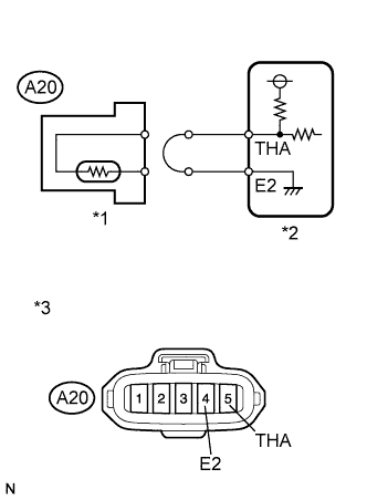
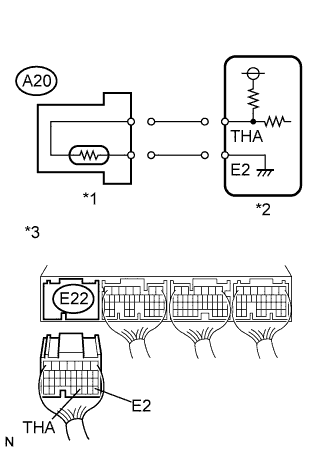
Text in Illustration *1 Intake Air Temperature Sensor *2 ECM *3 Front view of wire harness connector
(to Mass Air Flow Meter Sub-assembly)
Disconnect the mass air flow meter sub-assembly connector.
-
Connect terminals 4 and 5 of the mass air flow meter sub-assembly wire harness side connector.
-
Replace the normal DLC3 cable (12 V specification) for the intelligent tester with the 24 V DLC3 cable.
Note
Be sure to use the 24 V DLC3 cable when connecting the intelligent tester to the DLC3. Using the normal DLC3 cable (12 V specification) will cause damage to the tester.
-
Connect the intelligent tester to the DLC3.
-
Turn the ignition switch to ON.
-
Enter the following menus: Powertrain / Engine and ECT / Data List / Intake Air.
-
Read the value.
Standard 140°C (284°F) -
Reconnect the mass air flow meter sub-assembly connector.
NG
READ VALUE USING INTELLIGENT TESTER (CHECK FOR OPEN IN ECM) Click here
OK 
REPLACE MASS AIR FLOW METER SUB-ASSEMBLY Click here
-
-
READ VALUE USING INTELLIGENT TESTER (CHECK FOR OPEN IN ECM)
-
Text in Illustration *1 Intake Air Temperature Sensor *2 ECM *3 Component with harness connected
(ECM)
Disconnect the mass air flow meter sub-assembly connector.
-
Connect terminals THA and E2 of the ECM connector.
Tech Tips
Before checking, perform a visual and contact pressure check on the ECM connector.
-
Replace the normal DLC3 cable (12 V specification) for the intelligent tester with the 24 V DLC3 cable.
Note
Be sure to use the 24 V DLC3 cable when connecting the intelligent tester to the DLC3. Using the normal DLC3 cable (12 V specification) will cause damage to the tester.
-
Connect the intelligent tester to the DLC3.
-
Turn the ignition switch to ON.
-
Turn the tester on.
-
Enter the following menus: Powertrain / Engine and ECT / Data List / Intake Air.
-
Read the value.
Standard 140°C (284°F) -
Reconnect the mass air flow meter sub-assembly connector.
NG
REPLACE ECM Click here
OK
REPAIR OR REPLACE HARNESS OR CONNECTOR (ECM - MASS AIR FLOW METER SUB-ASSEMBLY)
-
-
READ VALUE USING INTELLIGENT TESTER (CHECK FOR SHORT IN WIRE HARNESS)
-
Text in Illustration *1 Intake Air Temperature Sensor *2 ECM Disconnect the mass air flow meter sub-assembly connector.
-
Replace the normal DLC3 cable (12 V specification) for the intelligent tester with the 24 V DLC3 cable.
Note
Be sure to use the 24 V DLC3 cable when connecting the intelligent tester to the DLC3. Using the normal DLC3 cable (12 V specification) will cause damage to the tester.
-
Connect the intelligent tester to the DLC3.
-
Turn the ignition switch to ON.
-
Turn the tester on.
-
Enter the following menus: Powertrain / Engine and ECT / Data List / Intake Air.
-
Read the value.
Standard -40°C (-40°F) -
Reconnect the mass air flow meter sub-assembly connector.
NG
READ VALUE USING INTELLIGENT TESTER (CHECK FOR SHORT IN ECM) Click here
OK
REPLACE MASS AIR FLOW METER SUB-ASSEMBLY Click here
-
-
READ VALUE USING INTELLIGENT TESTER (CHECK FOR SHORT IN ECM)
-
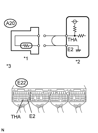
Text in Illustration *1 Intake Air Temperature Sensor *2 ECM *3 Rear view of wire harness connector
(to ECM)
Disconnect the mass air flow meter sub-assembly connector.
-
Disconnect the ECM connector.
-
Replace the normal DLC3 cable (12 V specification) for the intelligent tester with the 24 V DLC3 cable.
Note
Be sure to use the 24 V DLC3 cable when connecting the intelligent tester to the DLC3. Using the normal DLC3 cable (12 V specification) will cause damage to the tester.
-
Connect the intelligent tester to the DLC3.
-
Turn the ignition switch to ON.
-
Turn the tester on.
-
Enter the following menus: Powertrain / Engine and ECT / Data List / Intake Air.
-
Read the value.
Standard -40°C (-40°F) -
Reconnect the mass air flow meter sub-assembly connector.
-
Reconnect the ECM connector.
NG
REPLACE ECM Click here
OK
REPAIR OR REPLACE HARNESS OR CONNECTOR (ECM - MASS AIR FLOW METER SUB-ASSEMBLY)
-