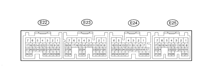
ECD SYSTEM TERMINALS OF ECM

Tech Tips
Each ECM terminal's standard voltage is shown in the table below.
In the table, first follow the information under "Condition". Look under "Terminal No. (Symbols)" for the terminals to be inspected. The standard voltage between the terminals is shown under "Specified Condition".
Use the illustration above as a reference for the ECM terminals.
| Terminal No. (Symbols) | Wiring Color | Terminal Description | Condition | Specified Condition |
|---|---|---|---|---|
| E24-2 (BATT) - E23-7 (E1) | L-R - BR | Battery (for measuring battery voltage and for ECM memory) | Constant | 11 to 14 V |
| E25-16 (IGSW) - E23-7 (E1) | GR - BR | Ignition switch | Ignition switch ON | 11 to 14 V |
| E25-1 (+B) - E23-7 (E1) | B-R - BR | Power source of ECM | Ignition switch ON | 11 to 14 V |
| E25-13 (MREL) - E23-7 (E1) | GR-R - BR | ENG-3 relay operation signal | Ignition switch ON | 11 to 14 V |
| E25-13 (MREL) - E23-7 (E1) | GR-R - BR | ENG-3 relay operation signal | 5 seconds pass after ignition switch off | 0 to 2 V |
| E22-18 (VC) - E23-7 (E1) | L-B - BR | Power source of sensor (specific voltage) | Ignition switch ON | 4.5 to 5.5 V |
| E25-15 (SREL) - E23-7 (E1) | R-L - BR | GLOW MAIN relay operation signal | Ignition switch ON, glow indicator light on | 11 to 14 V |
| E25-15 (SREL) - E23-7 (E1) | R-L - BR | GLOW MAIN relay operation signal | Engine is warmed up: Idling | 0 to 2 V |
| E25-11 (GIND) - E23-7 (E1) | Y-G - BR | Glow indicator | Ignition switch ON, glow indicator light on | 0 to 2 V |
| E25-11 (GIND) - E23-7 (E1) | Y-G - BR | Glow indicator | Engine is warmed up: Idling | 18 to 27 V |
| E25-22 (VPA) - E25-28 (EPA) | BR-R - LG-B | Accelerator pedal position sensor (for engine control) | Ignition switch ON, accelerator pedal fully released | 0.6 to 1.0 V |
| E25-22 (VPA) - E25-28 (EPA) | BR-R - LG-B | Accelerator pedal position sensor (for engine control) | Ignition switch ON, accelerator pedal fully depressed | 2.8 to 3.6 V |
| E25-23 (VPA2) - E25-29 (EPA2) | R-W - GR-G | Accelerator pedal position sensor (for sensor malfunction detection) | Ignition switch ON, accelerator pedal fully released | 1.4 to 1.8 V |
| E25-23 (VPA2) - E25-29 (EPA2) | R-W - GR-G | Accelerator pedal position sensor (for sensor malfunction detection) | Ignition switch ON, accelerator pedal fully depressed | 3.6 to 4.4 V |
| E25-20 (VCPA) - E25-28 (EPA) | B-O - LG-B | Power source of accelerator pedal position sensor (for VPA) | Ignition switch ON | 4.5 to 5.5 V |
| E25-21 (VCP2) - E25-29 (EPA2) | G-W - GR-G | Power source of accelerator pedal position sensor (for VPA2) | Ignition switch ON | 4.5 to 5.5 V |
| E23-24 (VG) - E23-32 (EVG) | G - V-R | Mass air flow meter sub-assembly | Engine is warmed up: Idling | 1.5 to 1.9 V |
| E22-31 (THA) - E22-28 (E2) | V-G - R-B | Intake air temperature sensor (built into mass air flow meter sub-assembly) | Engine is warmed up: Idling, intake air temperature at 0 to 80°C (32 to 176°F) | 0.5 to 3.4 V |
| E22-20 (THIA) - E22-28 (E2) | Y-R - R-B | Intake air temperature sensor (after turbocharged) | Engine is warmed up: Idling, intake air temperature at 0 to 80°C (32 to 176°F) | 1.0 to 4.4 V |
| E22-19 (THW) - E22-28 (E2) | G-R - R-B | Engine coolant temperature sensor | Idling, engine coolant temperature at 80 to 120°C (176 to 248°F) | 0.2 to 1.0 V |
| E22-24 (#1) - E23-7 (E1) E22-23 (#2) - E23-7 (E1) E22-22 (#3) - E23-7 (E1) E22-21 (#4) - E23-7 (E1) |
P-L - BR LG - BR LG-B - BR GR - BR |
Injector assembly | Engine is warmed up: Idling | Pulse generation (See waveform 1) |
| E23-23 (G+) - E23-31 (G-) | R - G | Camshaft position sensor | Engine is warmed up: Idling | Pulse generation (See waveform 2) |
| E22-27 (NE+) - E22-34 (NE-) | B - W | Crankshaft position sensor | Engine is warmed up: Idling | Pulse generation (See waveform 2) |
| E25-18 (STP) - E23-7 (E1) | V - BR | Stop light switch assembly | Ignition switch ON, brake pedal depressed | 18 to 27 V |
| E25-18 (STP) - E23-7 (E1) | V - BR | Stop light switch assembly | Ignition switch ON, brake pedal released | 0 to 2 V |
| E25-8 (ST1-) - E23-7 (E1) | V-Y - BR | Stop light switch assembly (opposite to STP) | Brake pedal depressed | 0 to 2 V |
| E25-8 (ST1-) - E23-7 (E1) | V-Y - BR | Stop light switch assembly (opposite to STP) | Brake pedal released | 18 to 27 V |
| E25-17 (TC) - E23-7 (E1) | R-B - BR | Terminal TC of DLC3 | Ignition switch ON | 18 to 27 V |
| E23-18 (STA) - E23-7 (E1) | B-W - BR | Starter signal | Cranking | 6 V or more |
| E25-6 (TAC) - E23-7 (E1) | P - BR | Engine speed | Idling | Pulse generation (See waveform 3) |
| E25-9 (W) - E23-7 (E1) | Y-R - BR | MIL | MIL illuminated | 0 to 2 V |
| E25-9 (W) - E23-7 (E1) | Y-R - BR | MIL | MIL not illuminated | 18 to 27 V |
| E25-19 (SPD) - E23-7 (E1) | R-Y - BR | Speed signal from tachograph assembly | Ignition switch ON, driving wheel slowly rotated | Pulse generation (See waveform 4) |
| E23-28 (PIM) - E22-28 (E2) | P-G - R-B | Manifold absolute pressure sensor | Applied negative pressure of 93 kPa (697 mmHg, 27.5 in.Hg) | 0.25 to 0.4 V |
| E23-28 (PIM) - E22-28 (E2) | P-G - R-B | Manifold absolute pressure sensor | Applied positive pressure of 150 kPa (1128 mmHg, 44.3 in.Hg) | 1.0 to 1.4 V |
| E22-10 (IREL) - E23-7 (E1) | R - BR | EDU relay operation signal | Ignition switch off | 11 to 14 V |
| E22-10 (IREL) - E23-7 (E1) | R - BR | EDU relay operation signal | Idling | 0 to 2 V |
| E22-26 (PCR1) - E22-28 (E2) | L-W - R-B | Fuel pressure sensor (built into common rail assembly) | Idling (Approximately 30 MPa (306 kgf/cm2, 4351 psi)) |
1.3 to 1.7 V |
| E22-29 (THF) - E22-28 (E2) | Y - R-B | Fuel temperature sensor (built into injection or supply pump assembly) | Ignition switch ON | 1.2 to 1.6 V |
| E23-22 (VCG) - E23-31 (G-) | L-R - G | Camshaft position sensor | Ignition switch ON | 4.5 to 5.5 V |
| E22-2 (PCV+) - E22-1 (PCV-) | L - L-Y | Suction control valve (built into injection or supply pump assembly) | Idling | Pulse generation (See waveform 5) |
| E23-33 (EGLS) - E22-28 (E2) | G-Y - R-B | EGR position sensor (built into EGR valve assembly) | Ignition switch ON | 3.8 to 4.2 V |
| E23-33 (EGLS) - E22-28 (E2) | G-Y - R-B | EGR position sensor (built into EGR valve assembly) | Engine is warmed up, Idling | 3.0 to 3.5 V |
| E23-3 (EGRS) - E23-7 (E1) | G - BR | EGR valve assembly | Ignition switch ON | 0 to 2 V |
| E23-3 (EGRS) - E23-7 (E1) | G - BR | EGR valve assembly | Engine is warmed up, engine speed 1500 rpm | Pulse generation (See waveform 6) |
| E22-25 (INJF) - E23-7 (E1) | B - BR | Injector driver assembly | Idling | Pulse generation (See waveform 7) |
| E23-20 (VLU) - E22-28 (E2) | Y-B - R-B | Throttle position sensor (built into diesel throttle body assembly) | Throttle valve fully closed | 2.6 to 3.0 V |
| E23-20 (VLU) - E22-28 (E2) | Y-B - R-B | Throttle position sensor (built into diesel throttle body assembly) | Throttle valve fully open | 1.4 to 1.8 V |
| E23-4 (LUSL) - E23-7 (E1) | W - BR | Throttle actuator (built into diesel throttle body assembly) duty signal | Accelerator pedal released → Accelerator pedal depressed (when throttle actuator is operating) | Pulse generation (See waveform 8) |
| E23-1 (THCO) - E22-28 (E2) | W-L - R-B | Exhaust gas temperature sensor (downstream) | Engine is warmed up, idling | 4.5 to 4.9 V |
| E23-2 (THCI) - E22-28 (E2) | W-R - R-B | Exhaust gas temperature sensor (upstream) | Engine is warmed up, idling | 4.5 to 4.9 V |
| E23-27 (PEX) - E22-28 (E2) | P-L - R-B | Differential pressure sensor assembly | Engine is warmed up, idling | 0.5 to 1.0 V |
| E24-15 (RGSW) - E23-7 (E1) | P-L - BR | DPF switch signal | DPF switch on | 18 to 27 V |
| E24-15 (RGSW) - E23-7 (E1) | P-L - BR | DPF switch signal | DPF switch off | 0 to 2 V |
| E23-8 (EXB) - E23-7 (E1) | P-L - BR | Exhaust brake | Exhaust brake operating | 11 to 14 V |
| E25-10 (W2) - E23-7 (E1) | B-W - BR | DPF indicator | DPF indicator on (ignition switch ON) | 0 to 2 V |
| E25-10 (W2) - E23-7 (E1) | B-W - BR | DPF indicator | DPF indicator off (idling) | 18 to 27 V |
| E23-16 (PMB) - E23-7 (E1) | B-W - BR | DPF warning buzzer (vacuum warning buzzer assembly) | Buzzer off | 18 to 27 V |
| E23-16 (PMB) - E23-7 (E1) | B-W - BR | DPF warning buzzer (vacuum warning buzzer assembly) | Buzzer on | 0 to 2 V |
| E24-16 (NUSW) - E23-7 (E1) | B-O - BR | Exhaust brake neutral switch assembly | Ignition switch ON, shift position is neutral | 11 to 14 V |
| E24-16 (NUSW) - E23-7 (E1) | B-O - BR | Exhaust brake neutral switch assembly | Ignition switch ON, shift position is not neutral | 0 to 2 V |
| E24-9 (CLSW) - E23-7 (E1) | O - BR | Exhaust brake clutch switch (exhaust retarder switch assembly) | Clutch pedal depressed | 0 to 2 V |
| E24-9 (CLSW) - E23-7 (E1) | O - BR | Exhaust brake clutch switch (exhaust retarder switch assembly) | Clutch pedal released | 18 to 27 V |
| E24-13 (EXSW) - E23-7 (E1) | L-W - BR | Exhaust brake switch (turn signal switch assembly) | Exhaust brake switch on | 18 to 27 V |
| E24-13 (EXSW) - E23-7 (E1) | L-W - BR | Exhaust brake switch (turn signal switch assembly) | Exhaust brake switch off | 0 to 2 V |
| E24-11 (HSW) - E23-7 (E1) | BR-W - BR | Warm up switch | Warm up switch on | 18 to 27 V |
| E24-11 (HSW) - E23-7 (E1) | BR-W - BR | Warm up switch | Warm up switch off | 0 to 2 V |
| E24-17 (CANH) - E23-7 (E1) | W - BR | CAN communication line | Engine stopped, ignition switch ON | Pulse generation (See waveform 9) |
| E24-28 (CANL) - E23-7 (E1) | B - BR | CAN communication line | Engine stopped, ignition switch ON | Pulse generation (See waveform 10) |
| E24-21 (AC) - E23-7 (E1) | V-W - BR | Air conditioning signal | Air conditioning on | 18 to 27 V |
| E24-21 (AC) - E23-7 (E1) | V-W - BR | Air conditioning signal | Air conditioning off | 0 to 2 V |
| E24-19 (ACT) - E23-7 (E1) | G - BR | Air conditioning cut signal | Ignition switch ON | 18 to 27 V |
| E24-19 (ACT) - E23-7 (E1) | G - BR | Air conditioning cut signal | Air conditioning cut signal on | 0 to 2 V |
| E24-30 (ABS) - E23-7 (E1) | V-R - BR | Anti-lock brake system operation | Anti-lock brake system does not operate | 11 to 14 V |
| E24-30 (ABS) - E23-7 (E1) | V-R - BR | Anti-lock brake system operation | Anti-lock brake system operate | 0 to 2 V |
| E23-7 (E1) - Body ground | BR - Body ground | Ground circuit of ECM | Always | Below 1 Ω |
| E22-28 (E2) - Body ground | R-B - Body ground | Ground circuit of ECM | Always | Below 1 Ω |
| E22-7 (E01) - Body ground | BR - Body ground | Ground circuit of ECM | Always | Below 1 Ω |
| E22-6 (E02) - Body ground | BR - Body ground | Ground circuit of ECM | Always | Below 1 Ω |
| E23-19 (EC) - Body ground | W-B - Body ground | Ground circuit of ECM | Always | Below 1 Ω |
-
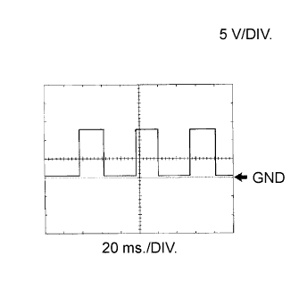
Waveform 1
-
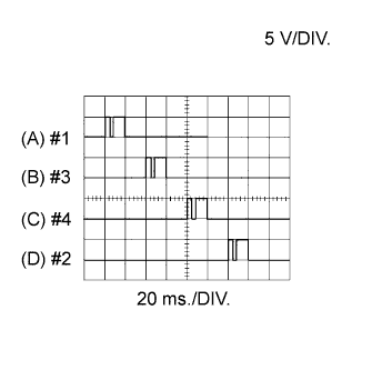
Injector Assembly No. 1 Injection Signal (A)
-
Injector Assembly No. 2 Injection Signal (B)
-
Injector Assembly No. 3 Injection Signal (C)
-
Injector Assembly No. 4 Injection Signal (D)
Terminal No. (Symbols) (A) E22-24 (#1) - E22-7 (E1)
(B) E22-22 (#3) - E22-7 (E1)
(C) E22-21 (#4) - E22-7 (E1)
(D) E22-23 (#2) - E22-7 (E1)
Tool Setting 5 V/DIV., 20 ms./DIV. Condition Engine is warmed up: Idling Tech Tips
The waveform varies depending on the injector injection.
-
-
Waveform 2
-
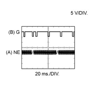
Crankshaft Position Sensor Signal (A)
-
Camshaft Position Sensor Signal (B)
Terminal No. (Symbols) (A) E22-27 (NE+) - E22-34 (NE-)
(B) E23-23 (G+) - E23-31 (G-)
Tool Setting 5 V/DIV., 20 ms./DIV. Condition Engine is warmed up: Idling Tech Tips
The waveform varies depending on the engine revolution.
-
-
Waveform 3
-
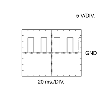
Engine Speed Signal
Terminal No. (Symbols) E25-6 (TAC) - E23-7 (E1) Tool Setting 5 V/DIV., 20 ms./DIV. Condition Idling Tech Tips
The wavelength becomes shorter as the engine speed increases.
-
-
Waveform 4
-
Vehicle Speed Signal
Terminal No. (Symbols) E25-19 (SPD) - E23-7 (E1) Tool Setting 5 V/DIV., 20 ms./DIV. Condition Ignition switch ON, driving wheel slowly rotated Tech Tips
The wavelength becomes shorter as the vehicle speed increases.
-
-
Waveform 5
-
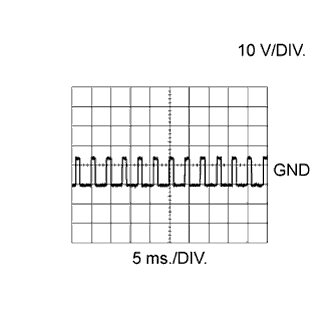
Suction Control Valve Signal
Terminal No. (Symbols) E22-2 (PCV+) - E22-1 (PCV-) Tool Setting 10 V/DIV., 5 ms./DIV. Condition Idling Tech Tips
The waveform varies depending on the suction control valve operation.
-
-
Waveform 6
-
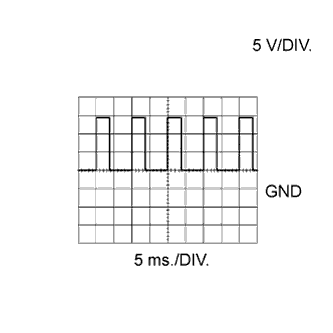
EGR Valve Assembly Signal
Terminal No. (Symbols) E23-3 (EGRS) - E23-7 (E1) Tool Setting 5 V/DIV., 5 ms./DIV. Condition Engine is warmed up, engine speed 1500 rpm
-
-
Waveform 7
-
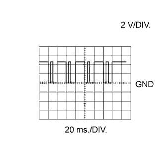
Injector Injection Confirmation Signal
Terminal No. (Symbols) E22-25 (INJF) - E23-7 (E1) Tool Setting 2 V/DIV., 20 ms./DIV. Condition Idling Tech Tips
The waveform varies depending on the injector injection.
-
-
Waveform 8
-
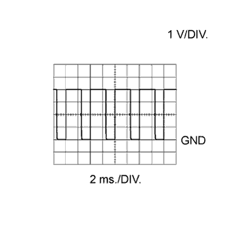
Throttle Actuator Signal
Terminal No. (Symbols) E23-4 (LUSL) - E23-7 (E1) Tool Setting 1 V/DIV., 2 ms./DIV. Condition Accelerator pedal released →
Accelerator pedal depressed
(when throttle actuator is operating)
Tech Tips
The waveform varies depending on the throttle valve operation.
-
-
Waveform 9
-
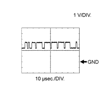
CAN Communication Signal
Terminal No. (Symbols) E24-17 (CANH) - E23-7 (E1) Tool Setting 1 V/DIV., 10 μsec./DIV. Condition Engine stopped, ignition switch ON Tech Tips
The waveform varies depending on the CAN communication signal.
-
-
Waveform 10
-
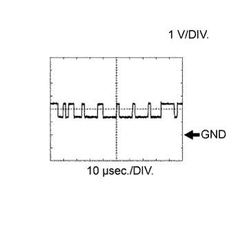
CAN Communication Signal
Terminal No. (Symbols) E24-28 (CANL) - E23-7 (E1) Tool Setting 1 V/DIV., 10 μsec./DIV. Condition Engine stopped, ignition switch ON Tech Tips
The waveform varies depending on the CAN communication signal.
-