ECD SYSTEM MIL Circuit
DESCRIPTION
If the ECM detects a malfunction, the MIL will be illuminated. The ECM then records the DTC in its memory.
WIRING DIAGRAM
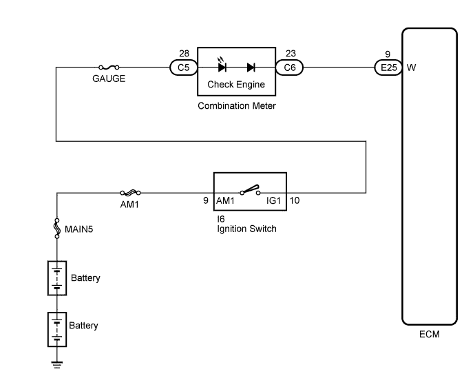
INSPECTION PROCEDURE
Note
After replacing the ECM, the new ECM needs registration Click here and initialization Click here.
PROCEDURE
-
CHECK MIL CONDITION
-
Use the table below to troubleshoot each problem symptom.
Result Condition Proceed to MIL remains ON A MIL is not illuminated B
B 
CHECK IF MIL IS ILLUMINATED Click here
A 
-
-
CHECK DTC OUTPUT
-
Connect the intelligent tester to the DLC3.
-
Turn the ignition switch to the ON position.
-
Turn the tester on.
-
Enter the following menu items: Powertrain / Engine and ECT / DTC.
-
Read the pending DTCs.
Result Display (DTC Output) Proceed to No DTCs A Engine related DTCs B
A 
GO TO DTC CHART
B
-
-
CHECK HARNESS AND CONNECTOR
-
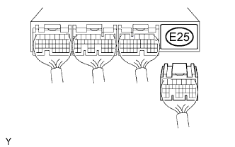
Disconnect the ECM connector.
-
Turn the ignition switch to the ON position.
-
Check that the MIL is not illuminated.
OK MIL is not illuminated. -
Reconnect the ECM connector.
NG
REPAIR OR REPLACE HARNESS OR CONNECTOR (COMBINATION METER - ECM)
OK 
REPLACE ECM
-
-
CHECK IF MIL IS ILLUMINATED
-
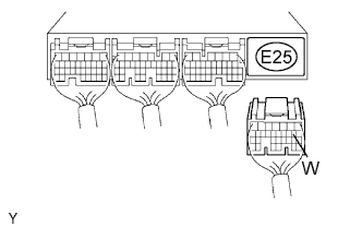
Disconnect the ECM connector.
-
Using a service wire, connect terminal W of the ECM and body ground.
-
Check if the MIL is illuminated when the ignition switch is turned to the ON position.
OK MIL is illuminated. -
Reconnect the ECM connector.
NG
CHECK COMBINATION METER ASSEMBLY (MIL CIRCUIT) Click here
OK
REPLACE ECM
-
-
CHECK COMBINATION METER ASSEMBLY (MIL CIRCUIT)
-
Check the combination meter circuit Click here.
OK Combination meter circuit is normal.
NG
REPAIR OR REPLACE COMBINATION METER ASSEMBLY
OK
REPAIR OR REPLACE HARNESS OR CONNECTOR (COMBINATION METER - ECM)
-