ECD SYSTEM Starter Signal Circuit
DESCRIPTION
When the engine is being cranked, the intake air flow is slow, so fuel vaporization is poor. A rich mixture is therefore necessary in order to achieve good startability. While the engine is being cranked, the battery positive voltage is applied to terminal STA of the ECM. The starter signal is mainly used to increase the fuel injection volume for starting injection control and after-start injection control.
WIRING DIAGRAM
Refer to DTC P0617 Click here.
INSPECTION PROCEDURE
PROCEDURE
-
READ VALUE USING INTELLIGENT TESTER
-
Connect the intelligent tester to the DLC3.
-
Turn the ignition switch to the ON position.
-
Turn the tester on.
-
Enter the following menu items: Powertrain / Engine and ECT / Data List / Starter Signal.
-
Read the value.
OK Ignition Switch Condition ON START Starter Signal OFF ON
NG 
CHECK STARTER RELAY ASSEMBLY (POWER SOURCE) Click here
OK 
CHECK FOR INTERMITTENT PROBLEMS
-
-
CHECK STARTER RELAY ASSEMBLY (POWER SOURCE)
-
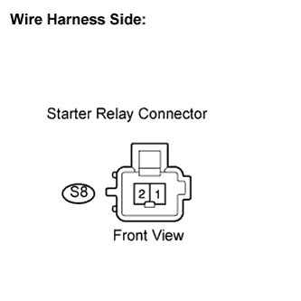
Disconnect the starter relay connector.
-
Measure the voltage according to the value(s) in the table below.
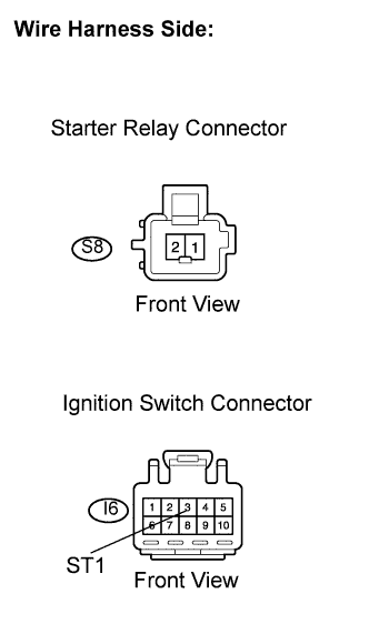
Standard voltage Tester Connection Condition Specified Condition S8-1 - S8-2 Engine cranking 18 to 27 V -
Reconnect the starter relay connector.
NG
INSPECT FUSE (AM1 FUSE) Click here
OK 
-
-
CHECK HARNESS AND CONNECTOR (IGNITION SWITCH - ECM)
-
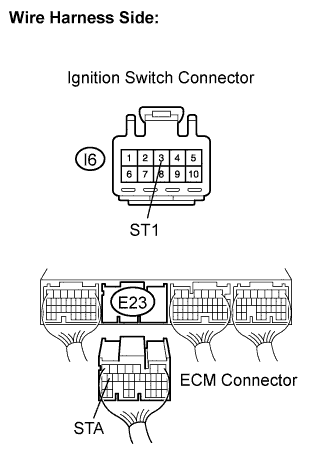
Disconnect the ignition switch connector.
-
Disconnect the ECM connector.
-
Measure the resistance according to the value(s) in the table below.
Standard resistance Check for open Tester Connection Condition Specified Condition I6-3 (ST1) - E23-18 (STA) Always Below 1 Ω Check for short Tester Connection Condition Specified Condition I6-3 (ST1) or E23-18 (STA) - Body ground Always 10 kΩ or higher -
Reconnect the ignition switch connector.
-
Reconnect the ECM connector.
NG 
REPAIR OR REPLACE HARNESS OR CONNECTOR (IGNITION SWITCH - ECM)
OK
REPLACE ECM
-
-
INSPECT FUSE (AM1 FUSE)
-
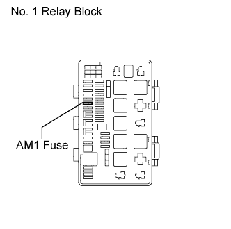
Remove the AM1 fuse from the No. 1 relay block.
-
Measure the resistance according to the value(s) in the table below.
Standard resistance Tester Connection Condition Specified Condition 1 - 2 Always Below 1 Ω -
Reconnect the AM1 fuse.
NG
REPLACE FUSE (AM1 FUSE)
OK
-
-
INSPECT STARTER RELAY ASSEMBLY
-
Inspect the starter relay Click here.
NG
REPLACE STARTER RELAY ASSEMBLY
OK
-
-
INSPECT IGNITION SWITCH ASSEMBLY
-
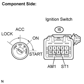
Disconnect the ignition switch connector.
-
Measure the resistance according to the value(s) in the table below.
Standard resistance Tester Connection Condition Specified Condition All terminals LOCK 10 kΩ or higher I6-9 (AM1) - I6-3 (ST1) STRT Below 1 Ω -
Reconnect the ignition switch connector.
NG
REPLACE IGNITION SWITCH ASSEMBLY
OK
-
-
CHECK HARNESS AND CONNECTOR (IGNITION SWITCH - STARTER RELAY)
-
Disconnect the ignition switch connector.
-
Disconnect the starter relay connector.
-
Measure the resistance according to the value(s) in the table below.
Standard resistance Check for open Tester Connection Condition Specified Condition I6-3 (ST1) - S8-1 Always Below 1 Ω Check for short Tester Connection Condition Specified Condition I6-3 (ST1) or S8-1 - Body ground Always 10 kΩ or higher -
Reconnect the starter relay connector.
-
Reconnect the ignition switch connector.
NG
REPAIR OR REPLACE HARNESS OR CONNECTOR (IGNITION SWITCH - STARTER RELAY)
OK
-
-
CHECK HARNESS AND CONNECTOR (STARTER RELAY - BODY GROUND)
-
Disconnect the starter relay connector.
-
Measure the resistance according to the value(s) in the table below.
Standard resistance Tester Connection Condition Specified Condition S8-2 - Body ground Always Below 1 Ω
NG
REPAIR OR REPLACE HARNESS OR CONNECTOR (STARTER RELAY - BODY GROUND)
OK
REPAIR OR REPLACE HARNESS OR CONNECTOR (BATTERY - IGNITION SWITCH)
-