ECD SYSTEM EDU Power Source Circuit
DESCRIPTION
An injector driver has been adopted to drive the injectors at high speeds. The injector driver has realized high-speed driving under high fuel pressure conditions through the use of a voltage converter that provides a high-voltage, quick-charging system. The ECM constantly monitors the injector driver and stops the engine or cuts off fuel supply to some cylinders if an abnormal condition is detected.
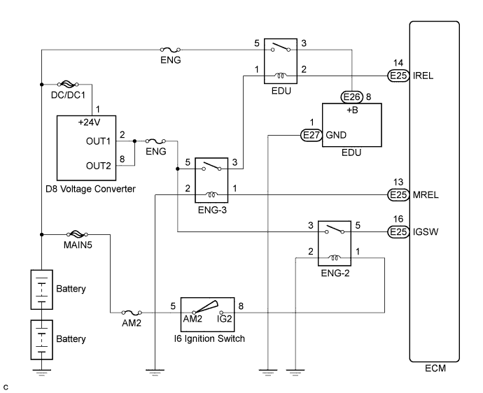
WIRING DIAGRAM
INSPECTION PROCEDURE
PROCEDURE
-
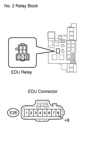
CHECK EDU (POWER SOURCE)
-
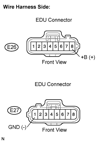
Disconnect the EDU connector.
-
Turn the ignition switch to the ON position.
-
Measure the voltage according to the value(s) in the table below.
Standard voltage Tester Connection Condition Specified Condition E26-8 (+B) - E27-1 (GND) Ignition switch in the ON position 18 to 27 V -
Reconnect the EDU connector.
NG 
INSPECT EDU RELAY Click here
OK 
REPLACE EDU
-
-
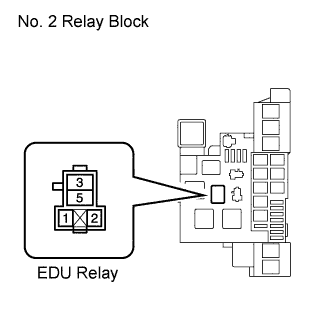
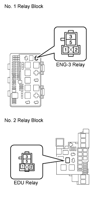
INSPECT EDU RELAY
-

Remove the EDU relay from the No. 2 relay block.
-
Measure the resistance according to the value(s) in the table below.
Standard resistance Tester Connection Condition Specified Condition 3 - 5 Battery voltage not applied 10 kΩ or higher 3 - 5 Battery voltage applied to terminals 1 and 2 Below 1 Ω -
Reinstall the EDU relay.
NG 
REPLACE EDU RELAY
OK 
-
-
INSPECT FUSE (ENG FUSE)
-
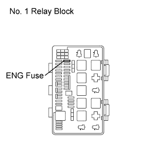
Remove the ENG fuse from the No. 1 relay block.
-
Measure the resistance according to the value(s) in the table below.
Standard resistance Tester Connection Condition Specified Condition 1 - 2 Always Below 1 Ω -
Reinstall the ENG fuse.
NG
REPLACE FUSE (ENG FUSE)
OK
-
-
CHECK HARNESS AND CONNECTOR (EDU RELAY - BATTERY)
-
Remove the EDU relay from the No. 2 relay block.
-
Disconnect the negative battery terminal.
-
Disconnect the positive battery terminal.
-
Measure the resistance according to the value(s) in the table below.
Standard resistance Check for open Tester Connection Condition Specified Condition EDU relay terminal 5 - Positive battery terminal Always Below 1 Ω Check for short Tester Connection Condition Specified Condition EDU relay terminal 5 or Positive battery terminal - Body ground Always 10 kΩ or higher -
Reinstall the EDU relay.
-
Reconnect the positive battery terminal.
-
Reconnect the negative battery terminal.
NG
REPAIR OR REPLACE HARNESS OR CONNECTOR (EDU RELAY - BATTERY)
OK
-
-
CHECK HARNESS AND CONNECTOR (EDU RELAY - ENG-3 RELAY)
-
Remove the EDU relay from the No. 2 relay block.
-
Remove the ENG-3 relay from the No. 1 relay block.
-
Measure the resistance according to the value(s) in the table below.
Standard resistance Check for open Tester Connection Condition Specified Condition EDU relay terminal 1 - ENG-3 relay terminal 3 Always Below 1 Ω Check for short Tester Connection Condition Specified Condition EDU relay terminal 1 or ENG-3 relay terminal 3 - Body ground Always 10 kΩ or higher -
Reinstall the EDU relay.
-
Reinstall the ENG-3 relay.
NG
REPAIR OR REPLACE HARNESS OR CONNECTOR (EDU RELAY - ENG-3 RELAY)
OK
-
-
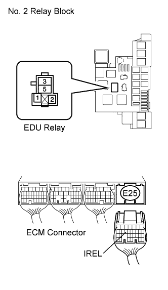
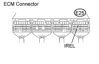
CHECK HARNESS AND CONNECTOR (EDU RELAY - ECM)
-
Remove the EDU relay from the No. 2 relay block.
-
Disconnect the ECM connector.
-
Measure the resistance according to the value(s) in the table below.
Standard resistance Check for open Tester Connection Condition Specified Condition EDU relay terminal 2 - E25-14 (IREL) Always Below 1 Ω Check for short Tester Connection Condition Specified Condition EDU relay terminal 2 or E25-14 (IREL) - Body ground Always 10 kΩ or higher -
Reconnect the ECM connector.
-
Reinstall the EDU relay.
NG
REPAIR OR REPLACE HARNESS OR CONNECTOR (EDU RELAY - ECM)
OK
-
-
CHECK HARNESS AND CONNECTOR (EDU RELAY - EDU)
-
Disconnect the EDU relay from the No. 2 relay block.
-
Disconnect the EDU connector.
-
Measure the resistance according to the value(s) in the table below.
Standard resistance Check for open Tester Connection Condition Specified Condition EDU relay terminal 3 - E26-8 (+B) Always Below 1 Ω Check for short Tester Connection Condition Specified Condition EDU relay terminal 3 or E26-8 (+B) - Body ground Always 10 kΩ or higher -
Reconnect the EDU connector.
-
Reinstall the EDU relay.
NG
REPAIR OR REPLACE HARNESS OR CONNECTOR (EDU RELAY - EDU)
OK
-
-
CHECK HARNESS AND CONNECTOR (EDU - BODY GROUND)
-
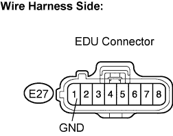
Disconnect the EDU connector.
-
Measure the resistance according to the value(s) in the table below.
Standard resistance Tester Connection Condition Specified Condition E27-1 (GND) - Body ground Always Below 1 Ω -
Reconnect the EDU connector.
NG
REPAIR OR REPLACE HARNESS OR CONNECTOR (EDU - BODY GROUND)
OK
-
-
CHECK ECM (IREL VOLTAGE)
-
Turn the ignition switch to the ON position.
-
Measure the voltage according to the value(s) in the table below.
Standard voltage Tester Connection Condition Specified Condition E25-14 (IREL) - Body ground Ignition switch in the ON position 11 to 14 V
NG
CHECK ECM POWER SOURCE CIRCUIT
OK
REPLACE ECM
-