ECD SYSTEM, Diagnostic DTC:U1123

| DTC Code | DTC Name |
|---|---|
| U1123 | Lost Communication with Variable Nozzle Type Turbo Charger Module |
DESCRIPTION
The CAN (Controller Area Network) is a serial data communication system for real time application. It is a multiplex communication system designed for on-vehicle use that provides a superior communication speed of 500 kbps and a capability to detect malfunctions. Through the combination of the CANH and CANL bus lines, the CAN is able to maintain communication based on differential voltage.
Tech Tips
-
Malfunctions in the CAN bus (communication line) can be checked from the DLC3. (except when the sub bus line of the DLC3 is open.)
-
Diagnostic codes (DTCs) related to CAN communication can be checked by using the intelligent tester.
-
The DLC3 is connected to the CAN communication line, but the CAN communication line cannot detect malfunctions in the DLC3 sub bus line.
| DTC No. | DTC Detection Condition | Trouble Area |
|---|---|---|
| U1123 | Both of the following conditions are met: (a) Ignition switch in the ON position (b) No communication between ECM and turbocharger actuator for 0.7 seconds |
|
WIRING DIAGRAM
Refer to DTC P0045 Click here.
INSPECTION PROCEDURE
PROCEDURE
-
CHECK WHETHER DTC OUTPUT RECURS (U1123)
-
Clear the DTCs Click here.
-
Turn the ignition switch off.
-
Turn the ignition switch to the ON position.
-
Turn the tester on.
-
Enter the following menu items: Powertrain / Engine and ECT / DTC.
-
Read the DTCs.
Result Result Proceed to DTC U1123 is output A No DTC output B
B 
CHECK FOR INTERMITTENT PROBLEMS
A 
-
-
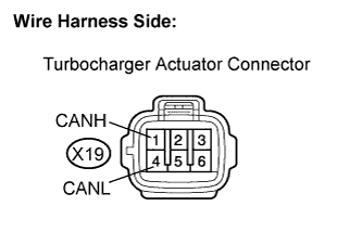
CHECK HARNESS AND CONNECTOR (CAN BUS LINE)
-
Disconnect the turbocharger connector.
-
Measure the resistance according to the value(s) in the table below.
Standard resistance Tester Connection Condition Specified Condition X19-1 (CANH) - X19-4 (CANL) Always 105 to 135 Ω -
Reconnect the turbocharger connector.
NG
REPAIR OR REPLACE HARNESS OR CONNECTOR (CAN BUS LINE)
OK
-
-
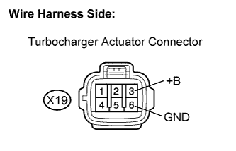
CHECK TURBOCHARGER SUB-ASSEMBLY (POWER SOURCE)
-
Disconnect the turbocharger connector.
-
Turn the ignition switch to the ON position.
-
Measure the voltage according to the value(s) in the table below.
Standard voltage Tester Connection Condition Specified Condition X19-3 (+B) - X19-6 (GND) Ignition switch on 11 to 14 V -
Reconnect the turbocharger connector.
NG 
CHECK HARNESS AND CONNECTOR (TURBOCHARGER - BODY GROUND) Click here
OK 
REPLACE TURBOCHARGER SUB-ASSEMBLY
-
-
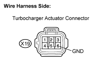
CHECK HARNESS AND CONNECTOR (TURBOCHARGER - BODY GROUND)
-
Disconnect the turbocharger connector.
-
Measure the resistance according to the value(s) in the table below.
Standard resistance Tester Connection Condition Specified Condition X19-6 (GND) - Body ground Always Below 1 Ω -
Reconnect the turbocharger connector.
NG
REPAIR OR REPLACE HARNESS OR CONNECTOR (TURBOCHARGER - BODY GROUND)
OK
REPAIR OR REPLACE HARNESS OR CONNECTOR (TURBOCHARGER - ENG-3 RELAY)
-