ECD SYSTEM, Diagnostic DTC:P2120, P2121, P2122, P2123, P2125, P2127, P2128, P2138

| DTC Code | DTC Name |
|---|---|
| P2120 | Throttle / Pedal Position Sensor / Switch "D" Circuit |
| P2121 | Throttle / Pedal Position Sensor / Switch "D" Circuit Range / Performance |
| P2122 | Throttle / Pedal Position Sensor / Switch "D" Circuit Low Input |
| P2123 | Throttle / Pedal Position Sensor / Switch "D" Circuit High Input |
| P2125 | Throttle / Pedal Position Sensor / Switch "E" Circuit |
| P2127 | Throttle / Pedal Position Sensor / Switch "E" Circuit Low Input |
| P2128 | Throttle / Pedal Position Sensor / Switch "E" Circuit High Input |
| P2138 | Throttle / Pedal Position Sensor / Switch "D" / "E" Voltage Correlation |
DESCRIPTION
Tech Tips
This is the repair procedure for the accelerator pedal position sensor.
-
This electrical throttle system does not use a throttle cable.
-
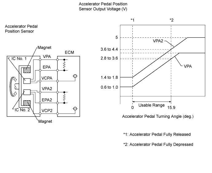
This accelerator pedal position sensor is non-contact type.
The accelerator pedal position sensor is mounted on the accelerator pedal and detects the opening angle of the accelerator pedal. Since this sensor is electronically controlled with Hall-effect elements, accurate control and reliability can be obtained. It has 2 sensors to detect the accelerator position and a malfunction of the accelerator position sensor.
In the accelerator pedal position sensor, the voltage applied to pedal terminals VPA and VPA2 of the ECM changes between 0 V and 5 V, in proportion to the opening angle of the accelerator pedal. The VPA is a signal to indicate the actual accelerator pedal opening angle which is used for engine control, and the VPA2 is a signal to indicate the information about the opening angle which is used for detecting a malfunction.
The ECM judges the current opening angle of the accelerator pedal from these signals input from terminals VPA and VPA2, and the ECM controls the throttle motor based on these signals.
| DTC No. | DTC Detection Condition | Trouble Area |
|---|---|---|
| P2120 | Condition (a) continues for 1 second or more: (a) VPA less than 0.2 V and VPA2 greater than 2.7 deg, or VPA greater than 4.8 V |
|
| P2121 | Conditions (a) and (b) continue for 1 second or more: (a) Difference between VPA and VPA2 exceeds the threshold (b) IDL is OFF |
|
| P2122 | Conditions (a) and (b) continue for 1 second or more: (a) VPA less than 0.2 V (b) VPA2 greater than 2.7 deg |
|
| P2123 | Condition (a) continues for 2 seconds or more: (a) VPA greater than 4.8 V |
|
| P2125 | Condition (a) continues for 1 second or more: (a) VPA2 less than 0.5 V and VPA greater than 2.7 deg, or VPA2 greater than 4.8 V and VPA greater than 0.2 V but less than 3.45 V |
|
| P2127 | Conditions (a) and (b) continue for 1 second or more: (a) VPA2 less than 0.5 V (b) VPA greater than 2.7 deg |
|
| P2128 | Conditions (a) and (b) continue for 2 seconds or more: (a) VPA2 greater than 4.8 V (b) VPA greater than 0.2 V but less than 3.45 V |
|
| P2138 | Condition (a) or (b) continues for 2 seconds or more: (a) Difference between VPA and VPA2 less than 0.02 V (b) VPA less than 0.2 V and VPA2 less than 0.5 V |
|
Tech Tips
When DTC P2120, P2122, P2123, P2125, P2127, P2128 or P2138 is detected, check the output voltage of the accelerator pedal position sensor by entering the following menus on the intelligent tester: Powertrain / Engine and ECT / Data List / Accel Position 1 and Accel Position 2.
| Trouble Area | Accelerator pedal position expressed as voltage output | |||
|---|---|---|---|---|
| Accelerator pedal released | Accelerator pedal depressed | |||
| Accel Position 1 | Accel Position 2 | Accel Position 1 | Accel Position 2 | |
| VC circuit open | 0 to 0.2 V | 0 to 0.2 V | 0 to 0.2 V | 0 to 0.2 V |
| VPA1 circuit open or ground short | 0 to 0.2 V | 1.4 to 1.8 V | 0 to 0.2 V | 3.6 to 4.4 V |
| VPA2 circuit open or ground short | 0.6 to 1.0 V | 0 to 0.2 V | 2.8 to 3.6 V | 0 to 0.2 V |
| EPA circuit open | 4.5 to 5.5 V | 4.5 to 5.5 V | 4.5 to 5.5 V | 4.5 to 5.5 V |
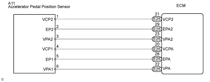
WIRING DIAGRAM
INSPECTION PROCEDURE
Tech Tips
Read freeze frame data using the intelligent tester. The ECM records vehicle and driving condition information as freeze frame data the moment a DTC is stored. When troubleshooting, freeze frame data can be helpful in determining whether the vehicle was running or stopped, whether the engine was warmed up or not, whether the air fuel ratio was lean or rich, as well as other data recorded at the time of a malfunction.
PROCEDURE
-
READ VALUE USING INTELLIGENT TESTER (ACCELERATOR POSITION)
-

Connect the intelligent tester to the DLC3.
-
Turn the ignition switch to the ON position.
-
Turn the tester on.
-
Enter the following menu items: Powertrain / Engine and ECT / Data List / Accel Position 1 and Accel Position 2.
-
Read the value.
Standard Accelerator Pedal Condition Accel Position 1 Accel Position 2 Released 0.6 to 1.0 V 1.4 to 1.8 V Depressed 2.8 to 3.6 V 3.6 to 4.4 V
NG 
CHECK WHETHER DTC OUTPUT RECURS Click here
OK 
-
-
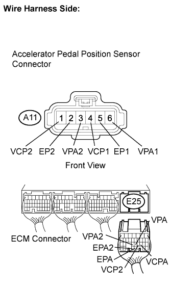
CHECK HARNESS AND CONNECTOR (ECM - ACCELERATOR PEDAL POSITION SENSOR)
-
Disconnect the accelerator pedal position sensor connector.
-
Disconnect the ECM connector.
-
Measure the resistance according to the value(s) in the table below.
Standard resistance Check for open Tester Connection Condition Specified Condition A11-1 (VCP2) - E25-21 (VCP2) Always Below 1 Ω A11-2 (EP2) - E25-29 (EPA2) Always Below 1 Ω A11-3 (VPA2) - E25-23 (VPA2) Always Below 1 Ω A11-4 (VCP1) - E25-20 (VCPA) Always Below 1 Ω A11-5 (EP1) - E25-28 (EPA) Always Below 1 Ω A11-6 (VPA1) - E25-22 (VPA) Always Below 1 Ω Check for short Tester Connection Condition Specified Condition A11-1 (VCP2) or E25-21 (VCP2) - Body ground Always 10 kΩ or higher A11-2 (EP2) or E25-29 (EPA2) - Body ground Always 10 kΩ or higher A11-3 (VPA2) or E25-23 (VPA2) - Body ground Always 10 kΩ or higher A11-4 (VCP1) or E25-20 (VCPA) - Body ground Always 10 kΩ or higher A11-5 (EP1) or E25-28 (EPA) - Body ground Always 10 kΩ or higher A11-6 (VPA1) or E25-22 (VPA) - Body ground Always 10 kΩ or higher -
Reconnect the accelerator pedal position sensor.
-
Reconnect the ECM connector.
NG 
REPAIR OR REPLACE HARNESS OR CONNECTOR (ECM - ACCELERATOR PEDAL POSITION SENSOR)
OK
-
-
CHECK ECM (VCPA AND VCP2 VOLTAGE)
-
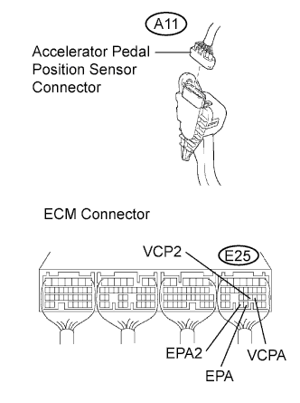
Disconnect the accelerator pedal position sensor connector.
-
Turn the ignition switch to the ON position.
-
Measure the voltage according to the value(s) in the table below.
Standard voltage Tester Connection Condition Specified Condition E25-20 (VCPA) - E25-28 (EPA) Ignition switch in the ON position 4.5 to 5.5 V E25-21 (VCP2) - E25-29 (EPA2) Ignition switch in the ON position 4.5 to 5.5 V -
Reconnect the accelerator pedal position sensor.
NG
REPLACE ECM
OK
-
-
REPLACE ACCELERATOR PEDAL
-
Replace the accelerator pedal assembly Click here.
NEXT
-
-
CHECK WHETHER DTC OUTPUT RECURS
-
Connect the intelligent tester to the DLC3.
-
Turn the ignition switch to the ON position.
-
Turn the tester on.
-
Clear the DTCs Click here.
-
Turn the ignition switch off.
-
Start the engine.
-
Run the engine at idle for 15 seconds or more.
-
Enter the following menu items: Powertrain / Engine and ECT / DTC.
-
Read the DTCs.
Result Display (DTC output) Proceed to P2120, P2121, P2122, P2123, P2125, P2127, P2128 or P2138 is output A No output B
B
END
A 
REPLACE ECM
-