ECD SYSTEM, Diagnostic DTC:P0617

| DTC Code | DTC Name |
|---|---|
| P0617 | Starter Relay Circuit High |
DESCRIPTION
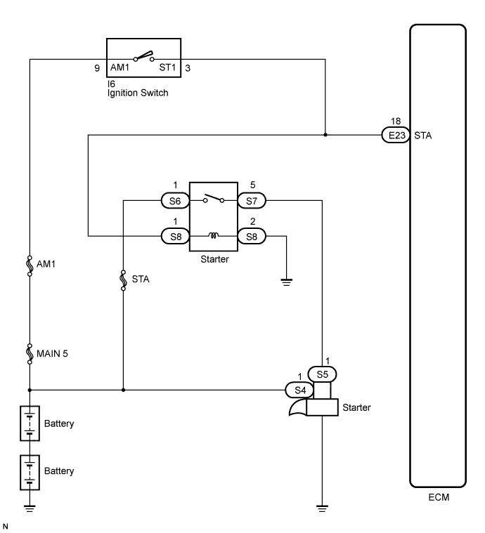
While the engine is being cranked, positive battery voltage is applied to terminal STA of the ECM.
If the ECM detects the starter control (STA) signal while the vehicle is being driven, it determines that there is a malfunction in the STA circuit. The ECM then illuminates the MIL and sets the DTC.
This monitor runs when the vehicle has been driven at 20 km/h (12.4 mph) for more than 20 seconds.
| DTC No. | DTC Detection Condition | Trouble Area |
|---|---|---|
| P0617 | When conditions (a), (b) and (c) are met, positive (+B) battery voltage of 10.5 V or more is applied to ECM for 20 seconds (1 trip detection logic): (a) Vehicle speed is more than 20 km/h (12.4 mph) (b) Engine speed is more than 1000 rpm (c) STA signal is ON |
|
WIRING DIAGRAM
INSPECTION PROCEDURE
Tech Tips
-
The following troubleshooting flowchart is based on the premise that the engine is cranked normally. If the engine does not crank, proceed to the problem symptoms table Click here.
-
Read freeze frame data using the intelligent tester. The ECM records vehicle and driving condition information as freeze frame data the moment a DTC is stored. When troubleshooting, freeze frame data can be helpful in determining whether the vehicle was running or stopped, whether the engine was warmed up or not, whether the air fuel ratio was lean or rich, as well as other data recorded at the time of a malfunction.
PROCEDURE
-
READ VALUE USING INTELLIGENT TESTER (STARTER SIGNAL)
-
Connect the intelligent tester to the DLC3.
-
Turn the ignition switch to the ON position.
-
Turn the tester on.
-
Enter the following menu items: Powertrain / Engine and ECT / Data List / Starter Signal.
-
Check the value displayed on the tester when the ignition switch is turned to the ON position and START position.
OK Ignition Switch Condition ON START Starter Signal OFF ON
NG 
INSPECT IGNITION SWITCH ASSEMBLY Click here
OK 
REPLACE ECM
-
-
INSPECT IGNITION SWITCH ASSEMBLY
-
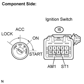
Disconnect the ignition switch connector.
-
Measure the resistance according to the value(s) in the table below.
Standard resistance Tester Connection Ignition Switch Position Specified Condition All terminals LOCK 10 kΩ or higher I6-9 (AM1) - I6-3 (ST1) START Below 1 Ω
NG 
REPLACE IGNITION SWITCH ASSEMBLY
OK 
-
-
CHECK HARNESS AND CONNECTOR (ECM - STARTER RELAY)
-
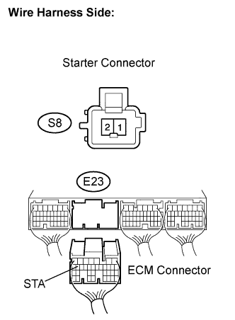
Disconnect the starter relay connector.
-
Disconnect the ECM connector.
-
Measure the resistance according to the value(s) in the table below.
Standard resistance Tester Connection Ignition Switch Position Specified Condition S8-1 or E23-18 (STA) - Body ground Always 10 kΩ or higher -
Reconnect the ECM connector.
-
Reconnect the starter relay connector.
NG
REPAIR OR REPLACE HARNESS OR CONNECTOR (ECM - STARTER RELAY)
OK
REPAIR OR REPLACE HARNESS OR CONNECTOR (ECM - IGNITION SWITCH)
-